Bending machine for machining auto parts and method of bending machine
A bending machine and accessories technology, applied in the field of auto parts processing, can solve the problems of prolonging the non-processing time, inconvenient operation, and endangering the personal safety of workers, so as to avoid the machine from hurting the workers, shorten the cutting time, and improve the processing efficiency Effect
- Summary
- Abstract
- Description
- Claims
- Application Information
AI Technical Summary
Problems solved by technology
Method used
Image

Examples
Embodiment 1
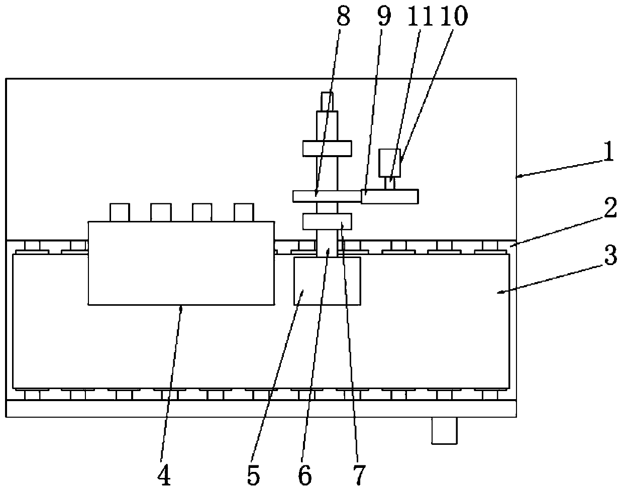
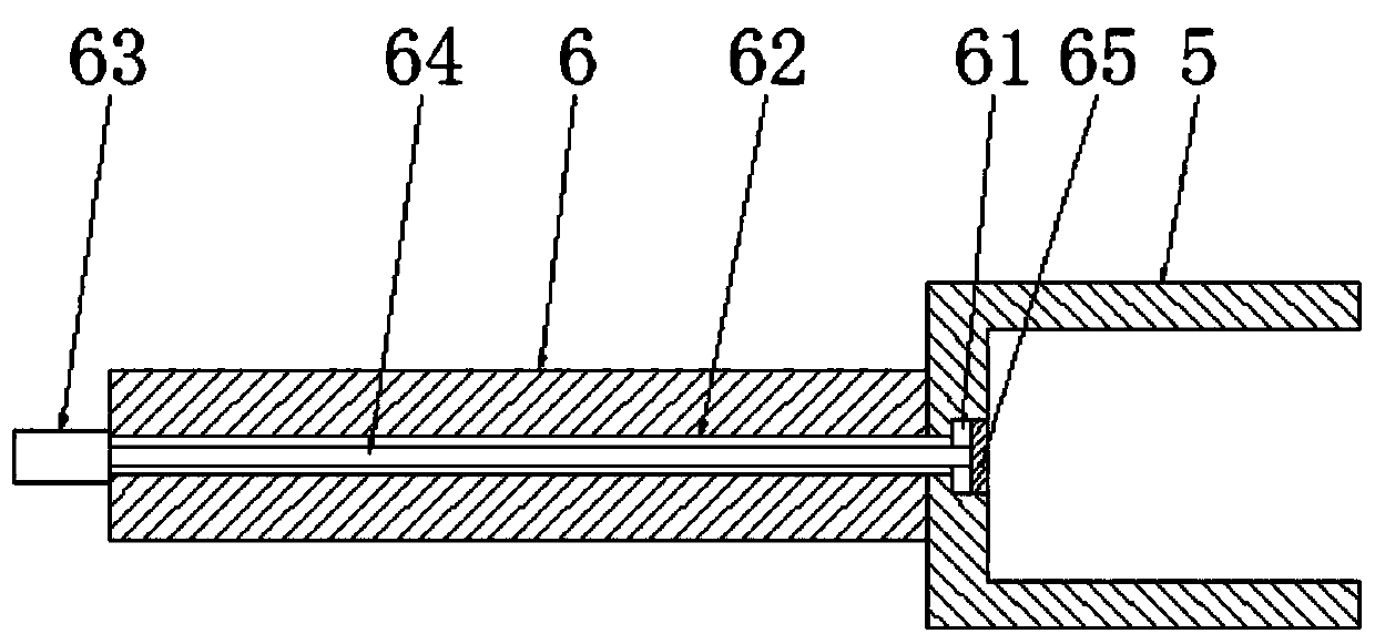
[0030] See Figure 1-2, a bending machine for auto parts processing, including a seat frame 1, a conveying groove 2 is provided on the top side of the seat frame 1, and a conveying mechanism 3 is arranged in the conveying groove 2, and the conveying mechanism 3 is a belt Type feeder, the top of the seat frame 1 is fixedly equipped with a feeding mechanism 4 and two brackets 7 matched with the conveying mechanism 3, and the two brackets 7 are arranged side by side on the right side of the feeding mechanism 4, two The bracket 7 is jointly rotated and connected with a bending rod 6, and one end of the bending rod 6 is fixedly connected with a bending arm 5 that is matched with the feeding mechanism 4 and the conveying mechanism 3 respectively, and the middle part of the bending rod 6 is sleeved with a Driven gear 8, the top of described seat frame 1 is also fixedly installed with bending motor 10, and described bending motor 10 is arranged on the right side of bending rod 6, and ...
Embodiment 2
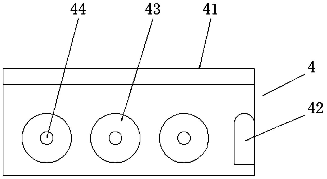
[0033] See image 3 , the difference from Embodiment 1 is: the feeding mechanism 4 includes a material rack 41, the material rack 41 is an L-shaped structure, and the material rack 41 is fixedly installed on the rear side of the delivery tank 2, and the inner cavity of the material rack 41 One end near the bending arm 5 is fixedly equipped with a bending plate 42, the top surface of the bending plate 42 is an arc surface, and the inner cavity of the material rack 41 is provided with some conveying rollers 43, and all the conveying rollers 43 is arranged side by side in parallel, and the conveying roller 43 is connected to the material rack 41 through the roller shaft 44. One end of the roller shaft 44 penetrates the material rack 41 and is connected to the external motor (not shown in the figure) in rotation. The outer motor cooperates with the roller shaft 44 to drive the conveying roller 43 to rotate, thereby driving the workpiece to pass through the bending plate 42 and ins...
Embodiment 3
[0035] See Figure 4 The difference from Embodiment 1 is that: the tail end of the bending rod 6 is covered with a driven wheel 12, and the top of the seat frame 1 is also equipped with an auxiliary motor 16, and the auxiliary motor 16 is rotatably connected with a second Two rotating shafts 15, the second rotating shaft 15 is fixedly connected with the driving wheel 13 matched with the driven wheel 12, the driving wheel 13 and the driven wheel 12 are on the same straight line, and the driving wheel 13 and the driven wheel 12 pass through The chain belt 14 is connected, and the rotation direction of the auxiliary motor 16 is the same as that of the bending motor 10. The auxiliary motor 16 cooperates with the second rotating shaft 15 to drive the driving wheel 13 to rotate, and the driving wheel 13 drives the driven wheel 12 to rotate through the chain belt 14, and then Drive the bending rod 6 to rotate, thereby assisting the bending motor 10 to jointly drive the bending rod 6 ...
PUM
 Abstract
Description
Claims
Application Information
 - R&D
- Intellectual Property
- Life Sciences
- Materials
- Tech Scout
- Unparalleled Data Quality
- Higher Quality Content
- 60% Fewer Hallucinations
Browse by: Latest US Patents, China's latest patents, Technical Efficacy Thesaurus, Application Domain, Technology Topic, Popular Technical Reports.
© 2025 PatSnap. All rights reserved.Legal|Privacy policy|Modern Slavery Act Transparency Statement|Sitemap|About US| Contact US: help@patsnap.com