
Aluminum ingot code marking device

A technology of aluminum ingots and protective devices, applied in welding equipment, laser welding equipment, metal processing equipment and other directions, can solve the problems of impact, support plate support surface and special shape is not easy, laser head is easy to fall ash, etc., to ensure normal Use and avoid damage

Pending Publication Date: 2020-01-03
ZHEJIANG RUIQI TECH CO LTD
View PDF0 Cites 1 Cited by
  • Summary
  • Abstract
  • Description
  • Claims
  • Application Information

AI Technical Summary

Problems solved by technology

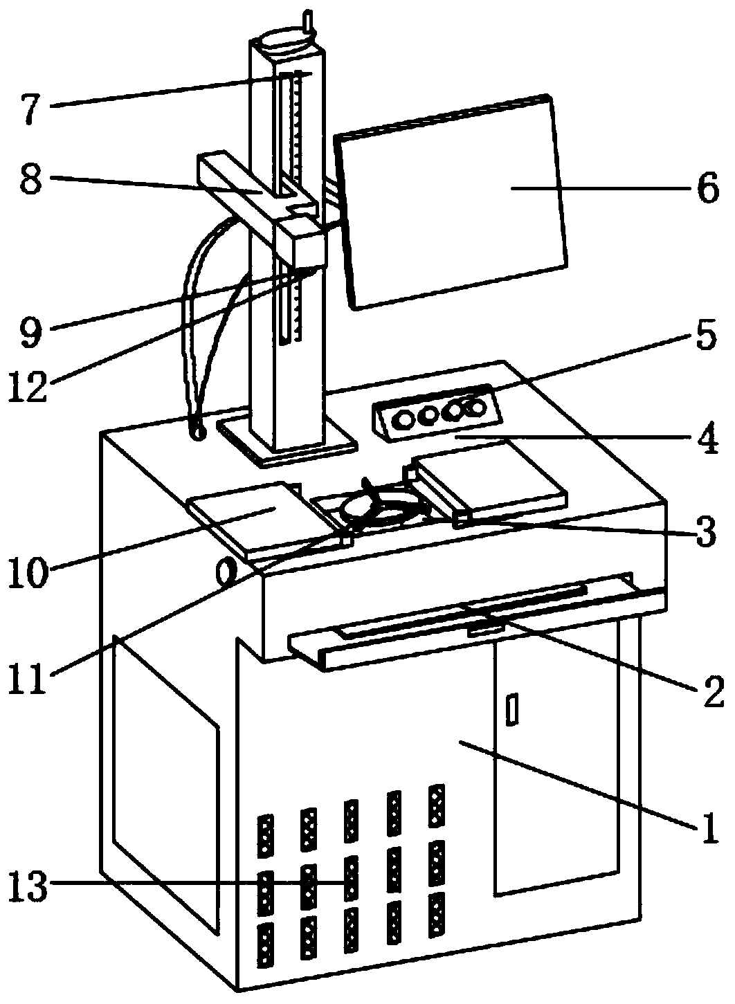
[0003] The main purpose of the present invention is to provide a coding device for aluminum ingots, which can effectively solve the problems in the background technology that the laser head is easy to fall ash or is hit, the support plate cannot change the support surface, and the problems of irregular shapes are not easy to code

Method used


Image

  • Aluminum ingot code marking device
  • Aluminum ingot code marking device
  • Aluminum ingot code marking device

Examples


Embodiment Construction

[0023] In order to make the technical means, creative features, goals and effects achieved by the present invention easy to understand, the present invention will be further described below in conjunction with specific embodiments.

[0024] In the description of the present invention, it should be noted that the terms "upper", "lower", "inner", "outer", "front end", "rear end", "both ends", "one end", "another end" The orientation or positional relationship indicated by etc. is based on the orientation or positional relationship shown in the drawings, and is only for the convenience of describing the present invention and simplifying the description, rather than indicating or implying that the referred device or element must have a specific orientation, use a specific Azimuth configuration and operation, therefore, should not be construed as limiting the invention. In addition, the terms "first" and "second" are used for descriptive purposes only, and should not be understood ...


PUM


Abstract

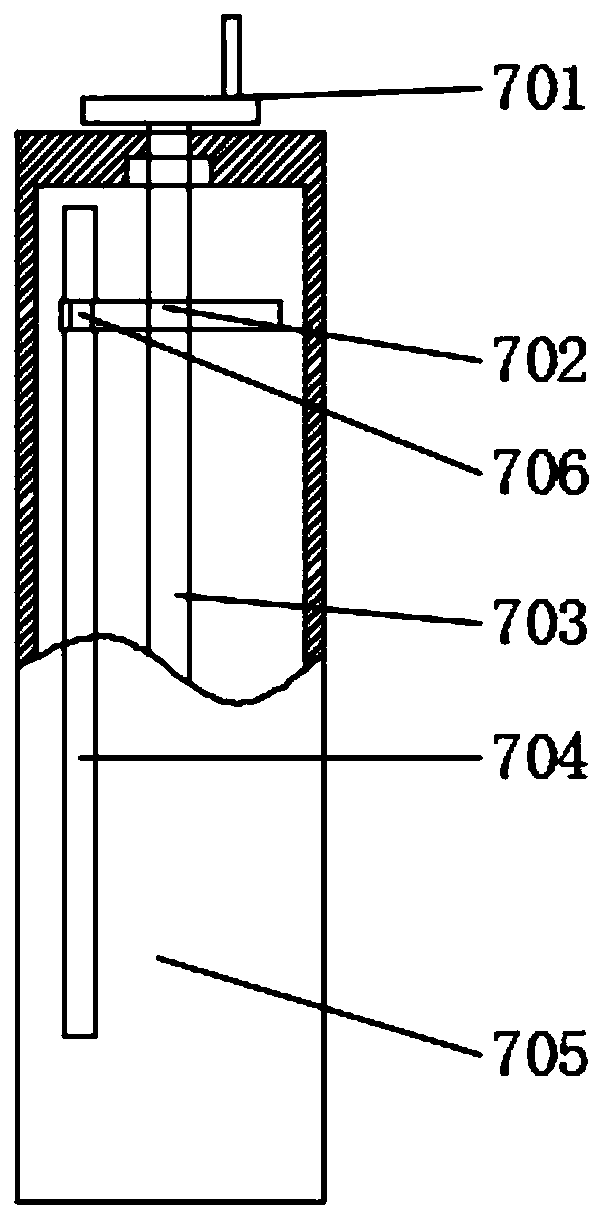
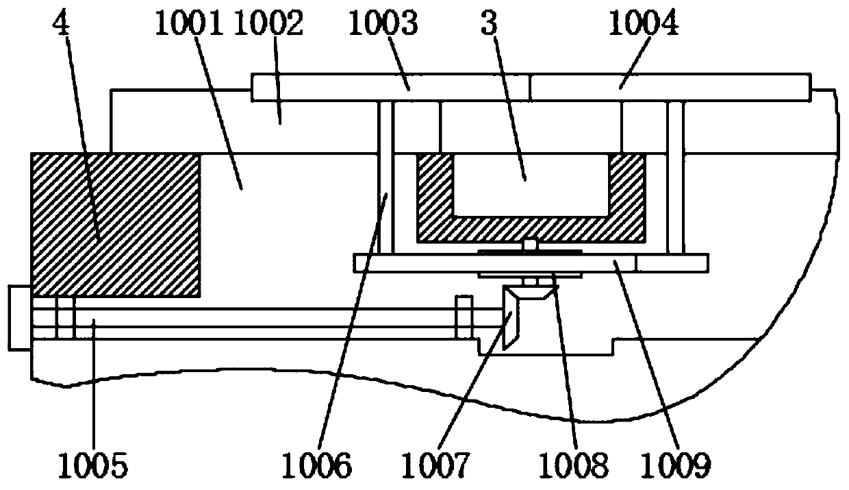
The invention discloses an aluminum ingot code marking device. The aluminum ingot code marking device comprises a device body and a workbench. The workbench is arranged on the upper surface of the device body. A lifting platform is arranged on the workbench. A clamping base is arranged on the upper part of the lifting platform. a protection device is welded to one end of the clamping base. A laserhead is arranged at one end of the clamping base and is arranged inside the protection device. Carrying platforms are arranged inside the workbench, at the top end of the workbench and below the laser head. A reserved groove is formed in the surface of the workbench and between the carrying platforms. A clamping device is arranged inside the reserved groove. With the aluminum ingot code marking device, because a large supporting surface can be obtained for large workpieces, and a slope of a silver ingot or some specially shaped workpieces can be clamped, and the device is applicable to different workpieces, a machined surface is smoother; and the laser head can be protected, not only is dust prevented from falling onto the laser head, but also the laser head is prevented from being damaged by collision.

Description

technical field [0001] The invention relates to the field of coding devices, in particular to a coding device for aluminum ingots. Background technique [0002] The coding device is a non-contact marking system controlled by a single-chip microcomputer, which is printed on different positions on the product surface to form various characters, patterns and other marks required. Among them, the fiber laser is used for coding on the metal, and the fiber laser is used. The laser beam makes permanent marks on the surface of various materials, and "engraves" traces through the physical changes of the surface materials through light energy, or burns part of the materials through light energy, showing the patterns and characters that need to be etched , barcodes and other graphics. However, the existing fiber lasers have certain disadvantages when coding. First, the laser head is easily hit or dusted when it is not in use, so that the laser head is damaged or the laser head falls i...

Claims


Application Information

Patent Timeline
Patent Type & Authority Applications(China)
IPC IPC(8): B23K26/02B23K26/362B23K26/70
CPCB23K26/362B23K26/02B23K26/702
Inventor 罗杨漾罗宏伟
Owner ZHEJIANG RUIQI TECH CO LTD
Learn More