Adjustable clamp for numerically-controlled machine tool

A CNC machine tool, adjustable technology, applied in the direction of clamping, manufacturing tools, metal processing machinery parts, etc., can solve the problems of parts processing that are not suitable for various sizes, waste of space, waste of time, etc., and achieve the effect of preventing damage to the device

Inactive Publication Date: 2020-01-03
夏涌
View PDF0 Cites 5 Cited by
  • Summary
  • Abstract
  • Description
  • Claims
  • Application Information

AI Technical Summary

Problems solved by technology

[0004] 1. It is more suitable for parts with standard shapes. It is difficult to clamp parts with special shapes such as crankshafts. Only special fixtures can be designed. However, there are many types of parts that need to be processed during processing, so it is necessary to design a large number of special fixtures, which not only wastes time. , also wastes space
[0005] 2. The fixtures in the prior art are not adjustable and have a small scope of application, so they are not suitable for processing parts of various sizes

Method used


Image

  • Adjustable clamp for numerically-controlled machine tool
  • Adjustable clamp for numerically-controlled machine tool
  • Adjustable clamp for numerically-controlled machine tool

Examples


specific Embodiment approach 1

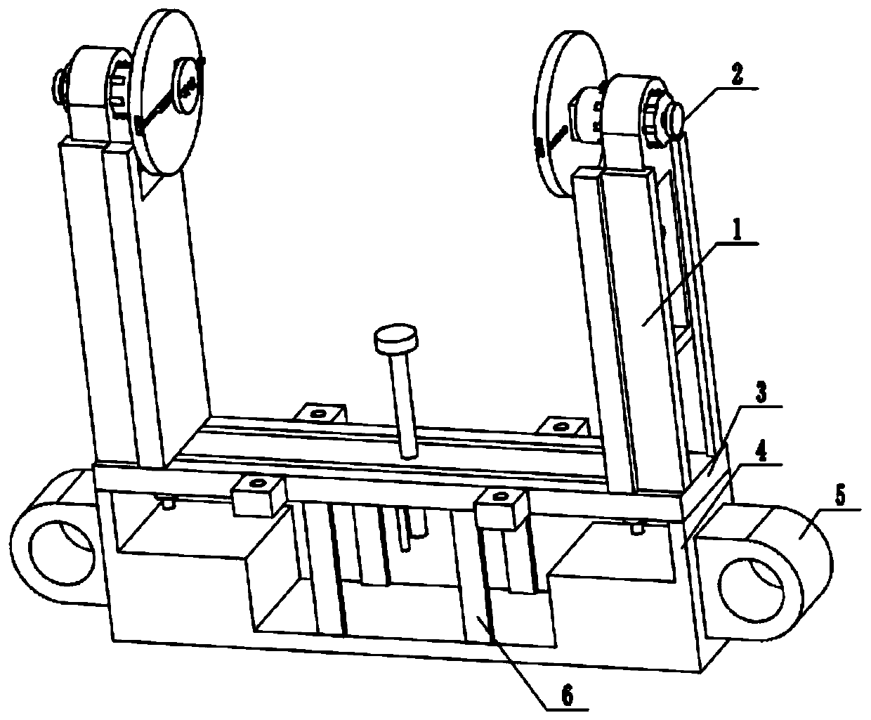
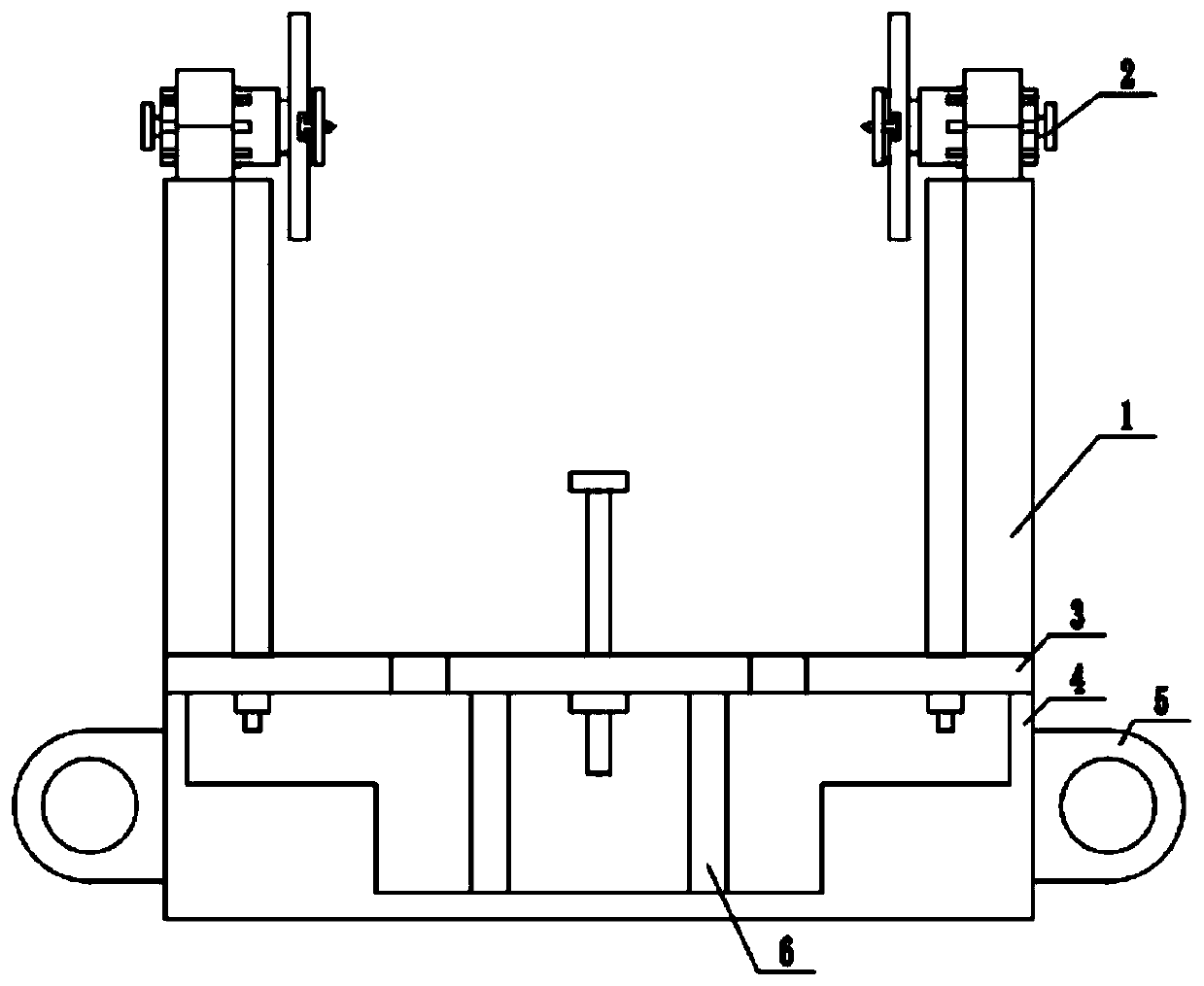
[0037] Combine below figure 1 , 2 In this embodiment, an adjustable clamp for a numerically controlled machine tool includes a lifting adjusting device 1, a workpiece clamping device 2, a workpiece supporting device 3, a fixed base 4, a lifting frame 5, and a support rod 6. The workpiece clamping device 2 It is installed on the lifting adjustment device 1 by keys. There are two lifting adjustment devices 1. The lifting adjustment device 1 is installed on the workpiece support device 3, the workpiece support device 3 is fixedly installed above the fixed base 4, and the lifting frame 5 is fixedly installed On the fixed base 4, the supporting rod 6 is fixedly installed on the workpiece supporting device 3, the other end of the supporting rod 6 is fixedly installed on the fixed base 4, and four supporting rods 6 are provided.

specific Embodiment approach 2

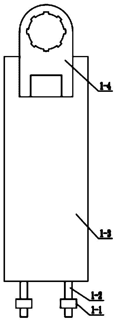
[0039] Combine below image 3 , 4 , 5, 6, 7 illustrate this embodiment, this embodiment will further illustrate the first embodiment, the lifting adjustment device 1 includes a control screw ring 1-1, a control screw 1-2, a support fixing plate 1-3, lifting Frame 1-4, L limit block 1-5, the control screw ring 1-1 is movably installed on the support device 3, the control screw ring 1-1 and the control screw 1-2 are connected by threads, and the control screw 1-2 is fixedly installed On the supporting fixing plate 1-3, the L restriction block 1-5 is fixedly installed on the supporting fixing plate 1-3, and the lifting frame 1-4 is in contact with the L restriction block 1-5 and the supporting fixing plate 1-3, respectively. To adjust the height and limit the movement direction of the lifting frame 1-4;

[0040] The lifting frame 1-4 includes a power motor 1-4-1, a transmission gear A1-4-2, a transmission gear B1-4-3, a gear connecting shaft 1-4-4, and a fixed frame body 1-4-5 , Ke...

specific Embodiment approach 3

[0042] Combine below Figure 8 , 9 , 10, 11, 12, and 13 illustrate this embodiment, and this embodiment further illustrates the first embodiment. The workpiece clamping device 2 includes a rotating handle 2-1, a handle connecting rod 2-2, a clamping mechanism connecting column 2-3. Clamping mechanism 2-4, rotating handle 2-1 is fixedly installed on the handle connecting rod 2-2, the handle connecting rod 2-2 is fixedly installed on the clamping mechanism connecting column 2-3, and the clamping mechanism is connected Multiple key grooves are provided on the column 2-3, and the clamping mechanism 2-4 is fixedly installed on the clamping mechanism connecting column 2-3;

[0043] The clamping mechanism 2-4 includes a fixed center 2-4-1, an eccentric adjusting plate 2-4-2, a fastening screw A2-4-3, an adjusting step bar 2-4-4, and a fixed chassis 2-4 -5. Support wheel 2-4-6, limit center 2-4-7, fastening screw B2-4-8, fixed center 2-4-1 is fixedly installed on eccentric adjustment pla...


PUM


Abstract

The invention relates to a machine tool clamp, in particular to an adjustable clamp for a numerically-controlled machine tool. The adjustable clamp comprises lifting adjusting devices, workpiece clamping devices, a workpiece supporting device, a fixed base, hoisting frames and supporting rods. The workpiece clamping devices are mounted on the lifting adjusting devices through keys, and the two lifting adjusting devices are mounted on the workpiece supporting device. The workpiece supporting device is fixedly mounted above the fixed base, and the hoisting frames are fixedly mounted on the fixedbase. The supporting rods are fixedly mounted on the workpieces supporting device, and the other ends of the supporting rods are fixedly mounted on the fixed base. The number of the supporting rods is four. According to the adjustable clamp, the height of the two ends and the distance between the two ends can be independently adjusted, and the device can adapt to parts of multiple sizes; the device is provided with a jacking device, and it can be avoided that the parts bear force to deform when machined, and consequently machining errors are caused; and due to the fact that the device is provided with the hoisting frames, a crane can be prevented from damaging the device in the device is hoisted.

Description

Technical field [0001] The invention relates to a fixture for machine tools, more specifically an adjustable fixture for numerical control machine tools. Background technique [0002] The machine tool is inseparable from the auxiliary device in the additional processing. The fixture is one of the more important auxiliary devices. The tight and stable type of the fixture directly affects the processing accuracy. During the processing, there are often some special shapes. Parts, crankshafts can be said to be a representative one. For clamping parts with special shapes, the prior art has many shortcomings. The shortcomings of the prior art will be described below. [0003] The disadvantages of the existing technology are: [0004] 1. It is more suitable for parts with standard shapes. It is more difficult to clamp special-shaped parts such as crankshafts. Only special fixtures can be designed. However, there are often many types of parts that need to be processed in processing, so it i...

Claims


Application Information

Patent Timeline
Patent Type & Authority Applications(China)
IPC IPC(8): B23Q3/06
CPCB23Q3/062
Inventor 夏涌
Owner 夏涌
Why Eureka
Try Eureka