Core pulling machine for smoke conveying pipes

The technology of conveying pipe and core-pulling machine is applied in the field of flue gas conveying pipe core-pulling machine, which can solve the problems of difficult core-pulling, large volume and heavy weight of flue gas conveying pipe, and achieves convenient sliding frame movement and high transmission efficiency. Effect

Active Publication Date: 2020-01-03
ZHEJIANG TUNA ENVIRONMENTAL SCI & TECH
View PDF8 Cites 1 Cited by
  • Summary
  • Abstract
  • Description
  • Claims
  • Application Information

AI Technical Summary

Problems solved by technology

The flue gas conveying pipe is usually large in size and heavy in weight, and the material of the mold core column used for shaping the shape inside it is usually metal, which is huge in weight and difficult to pull the core.

Method used


Image

  • Core pulling machine for smoke conveying pipes
  • Core pulling machine for smoke conveying pipes
  • Core pulling machine for smoke conveying pipes

Examples


Embodiment Construction

[0036]The present invention will be described in further detail below in conjunction with the accompanying drawings.

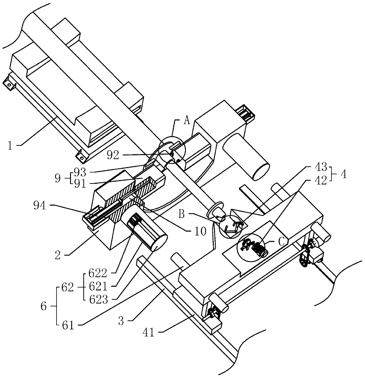
[0037] Such as figure 1 As shown, a core-pulling machine for flue gas conveying pipes includes a carrier frame 1, a positioning frame 2, a guide rail 3, and a core-pulling device 4. The carrier frame 1 is composed of a base and a lifting platform. The rubber hose is supported; the positioning frame 2 is fixed on the ground, and the positioning frame 2 remains fixed during the operation of the core pulling machine, and a positioning mechanism 9 for limiting the movement of the rubber hose is arranged on the positioning frame 2 .

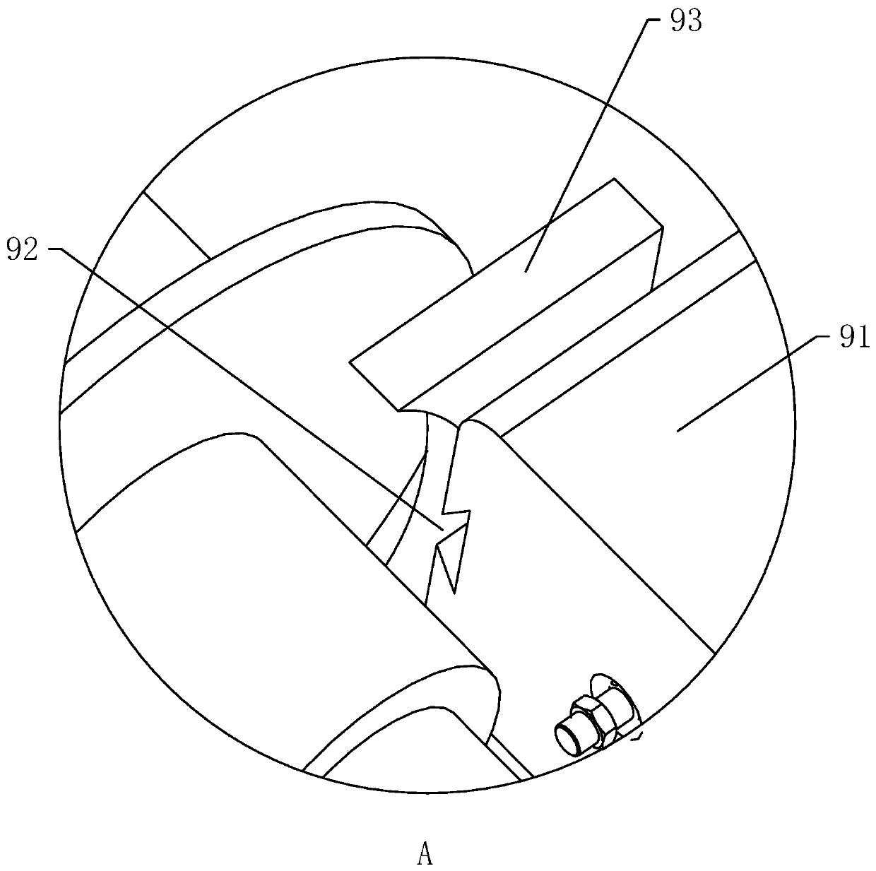
[0038] The positioning mechanism 9 comprises a positioning arm 91, a slideway 92, a positioning clamp 93, and a telescopic assembly 94. The positioning arm 91 is provided with two pieces, which are fixed on the positioning frame 2 and are respectively located on both sides of the positioning frame 2; the slideway 92 (see figure 2 ) ...


PUM


Abstract

The invention discloses a core pulling machine for smoke conveying pipes, relates to core pulling equipment, and is used for solving the problem of high difficulty of core pulling during production ofrubber pipes. The core pulling machine comprises a bearing frame for bearing the rubber pipes, a positioning frame for fixing the rubber pipes, guiding rails arranged on one side, far away from the bearing frame, of the positioning frame as well as a core pulling device glidingly arranged on the guiding rails; and the core pulling device comprises a sliding frame glidingly arranged on the guidingrails, a clamping mechanism arranged on the sliding frame and used for grasping mold core columns as well as a driving mechanism arranged on the sliding frame and used for driving the sliding frame to move along the guiding rails. The structure that the weight of the rubber pipes and the mold core columns is borne by the bearing frame, then the rubber pipes are fixed by the positioning frame andcore pulling is performed by the core pulling device on the sliding frame finally is adopted, and core pulling operation can be performed on the rubber pipes in various weight and sizes, so that the labor intensity of an operator can be reduced, the operation difficulty caused by the huge sizes of the mold core columns is reduced, and the purpose of facilitating the core pulling operation on the rubber pipes is achieved.

Description

technical field [0001] The invention relates to core-pulling equipment, in particular to a core-pulling machine for flue gas conveying pipes. Background technique [0002] Power plants and chemical plants usually produce sulfur-containing and nitrate-containing waste gases. If these waste gases are discharged directly, they will cause serious pollution to the environment, so they need to be purified before they are discharged. The treatment of these exhaust gases is usually transported to the purification device through pipelines, and then treated by spraying or catalytic decomposition. At present, plastic hoses are mostly used as conveying pipes in the industry. During the manufacturing process, these hoses are coated with glue on the core column of the mold and wound with glass fiber yarns. After the rubber is dried and solidified, it will be lined with high-strength glass. Fiber hose. [0003] These hoses are mainly used for flue gas transportation after molding, so the...

Claims


Application Information

Patent Timeline
IPC IPC(8): B29C45/33
CPCB29C45/33
Inventor 金猛马太余沈张生刘智邦高彬顾一飞
Owner ZHEJIANG TUNA ENVIRONMENTAL SCI & TECH
Why Eureka
Try Eureka