Rail vehicle roof drainage protection structure and drainage box

A technology for rail vehicles and protective structures, applied in the field of rail vehicles, can solve the problems of inconvenient removal, easy corrosion of threaded fasteners 300, cumbersome operation, etc., and achieves the effect of simple structure and avoiding poor drainage.

Active Publication Date: 2021-07-23
HUNAN CRRC INTELLIGENT TRANSPORT TECH CO LTD +1
View PDF7 Cites 0 Cited by
  • Summary
  • Abstract
  • Description
  • Claims
  • Application Information

AI Technical Summary

Problems solved by technology

In order to prevent the drain pipe from being blocked by leaves and other sundries, a drain baffle with a leak hole is usually installed on the upper part of the drain box. Although the drain baffle prevents leaves and other sundries from entering the drain box to a certain extent, it falls on the drain baffle. Leaves and other flaky debris on the roof are not easy to fall off from the baffle of the plane structure, so that the leakage hole is blocked by the leaves, resulting in poor drainage
In addition, there are two main installation methods for the existing drainage baffle: one is to install buckles 101 on the lower part of the drainage baffle 100, and use the buckles 101 to fasten on the drainage box. Although this installation method is more convenient, it is resistant to The impact and vibration performance is poor and not stable enough; the other is to set the installation block 200 on the inner wall of the drainage box, and the drainage baffle 100 and the installation block 200 are connected by threaded fasteners 300 (such as screws). Although this installation method is relatively It is stable, but the structure is relatively complicated, and the operation is cumbersome, and the threaded fastener 300 is easy to rust, which makes it impossible to remove and replace it. Once debris enters the drainage box, it is inconvenient to remove

Method used


Image

  • Rail vehicle roof drainage protection structure and drainage box
  • Rail vehicle roof drainage protection structure and drainage box
  • Rail vehicle roof drainage protection structure and drainage box

Examples


Embodiment 1

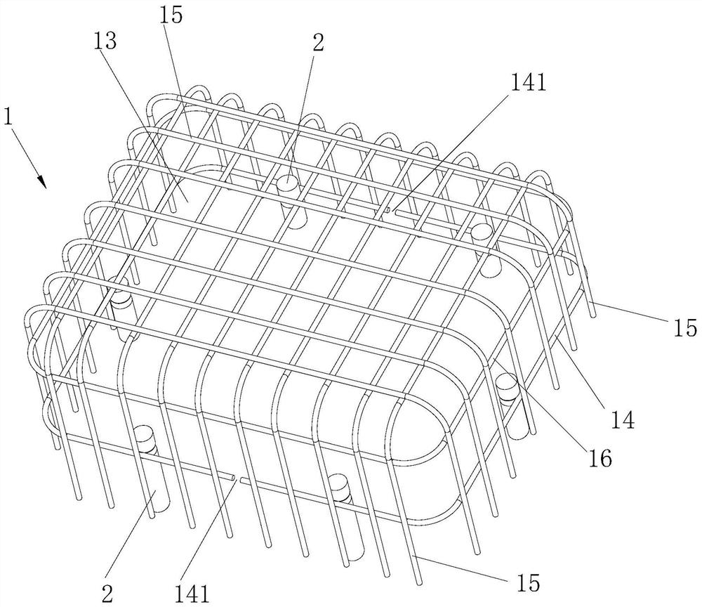
[0026] image 3 An embodiment of the rail vehicle roof drainage protection structure of the present invention is shown. The rail vehicle roof drainage protection structure of this embodiment includes a protective cover 1 and several mounting parts 2. The protective cover 1 includes a (Specifically the drainage box body 4) above the protective part 11 and the connecting part 12 located at the edge of the protective part 11, the protective part 11 is provided with a water leakage hole 13, the mounting part 2 is installed on the roof 3, and the connecting part 12 is downward Extend and connect with mounting part 2.

[0027] In the roof drainage protection structure of the present embodiment, the connecting portion 12 extends downwards and is connected with the mounting part 2 provided on the roof 3 to realize the installation of the protective cover 1, and the protective portion 11 with the water leakage hole 13 can prevent impurities such as leaves from When there are sundries ...

Embodiment 2

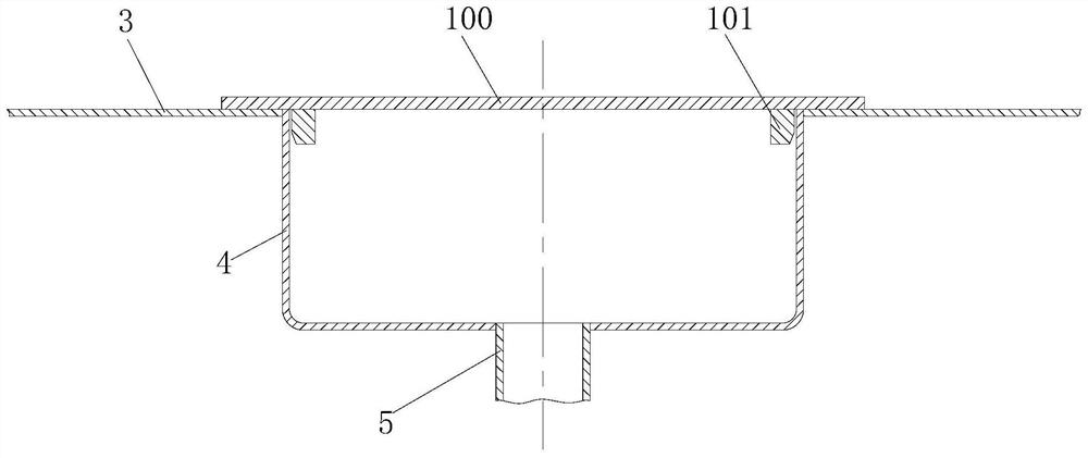
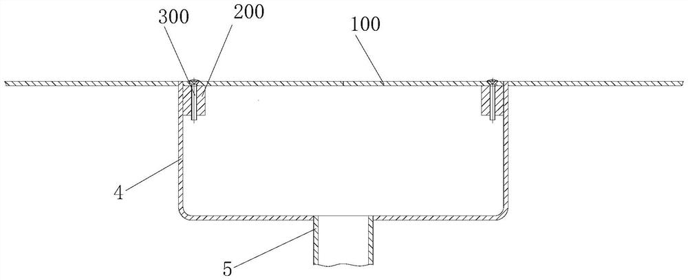
[0037] Figure 4 to Figure 5 An embodiment of the rail vehicle roof drainage box of the present invention is shown. The rail vehicle roof drainage box of this embodiment includes a drainage box body 4 and a drain pipe 5 arranged below the drainage box body 4, and also includes the above-mentioned In the rail vehicle roof drainage protection structure, the protection part 11 is located above the drainage box body 4 , and the connecting part 12 is located outside the drainage box body 4 .

[0038] The rail vehicle roof drainage box includes the above-mentioned drainage protection structure, so it also has the advantages of the above-mentioned drainage protection structure.


PUM


Abstract

The invention discloses a rail vehicle roof drainage protection structure, which includes a protective cover and several mounting parts. A water leakage hole is opened on the part, the mounting part is installed on the roof, and the connecting part extends downwards and is connected with the mounting part. The invention further discloses a rail vehicle roof drainage box, which includes a drainage box body and a drain pipe arranged under the drainage box body, and also includes the above-mentioned rail vehicle roof drainage protection structure, the protection part is located in the drainage box Above the body, the connecting part is located outside the drainage box. The invention has the advantages of being able to prevent sundries from falling into the drainage box, and avoiding obstruction of sundries to cause poor drainage, and the like.

Description

technical field [0001] The invention relates to rail vehicles, in particular to a rail vehicle roof drainage protection structure and a drainage box. Background technique [0002] For rail vehicles, in order to drain the roof, it is necessary to set up a drainage box to collect rainwater, and the bottom of the drainage box is connected to a drainpipe to discharge the collected rainwater. In order to prevent the drain pipe from being blocked by leaves and other sundries, a drain baffle with a leak hole is usually installed on the upper part of the drain box. Although the drain baffle prevents leaves and other sundries from entering the drain box to a certain extent, it falls on the drain baffle. Flake debris such as leaves on the top is not easy to fall off from the baffle plate of the planar structure, so that the leakage hole is blocked by the leaves, resulting in poor drainage. In addition, there are two main installation methods for the existing drainage baffle: one is t...

Claims


Application Information

Patent Timeline
Patent Type & Authority Patents(China)
IPC IPC(8): B61D17/12
CPCB61D17/12
Inventor 银应时杨勇刘湘萍李扬戈
Owner HUNAN CRRC INTELLIGENT TRANSPORT TECH CO LTD
Why Eureka
Try Eureka