
Method for generating liquid droplet array on microfluidic chip

A technology of microfluidic chips and microwell arrays, applied in biochemical equipment and methods, measurement/testing of microorganisms, fluid controllers, etc., can solve problems such as cross-contamination of micropores, high price and complexity of surfactants, etc. Achieve the effect of good physical isolation, convenient assembly and large tolerance

Active Publication Date: 2020-01-03
SHANGHAI JIAOTONG UNIV
View PDF4 Cites 7 Cited by
  • Summary
  • Abstract
  • Description
  • Claims
  • Application Information

AI Technical Summary

Problems solved by technology

[0008] The shortcomings of the existing technology mainly include the following points: In order to generate droplets with good uniformity in size, the droplet method requires precise control of the flow rates of two immiscible liquids. This process usually Fluid pumps and other instruments are needed, the overall instrument system will be more complex, the instrument volume is large, the system is relatively expensive, and the uniformity of the droplets is crucial to the accuracy and reliability of the analysis results such as digital PCR. In addition, in order to ensure There is no cross-contamination between the generated droplets (transfer of substance molecules between droplets) and to avoid fusion between droplets (two or more droplets contact each other and become a larger droplet), usually requires Use of surfactants
Surfactants are usually expensive and will affect the biochemical reactions in aqueous solution; the QuantStudio 3D digital PCR system requires many manual steps, the process of generating droplets is complicated, and it uses the organic phase (oil phase) to separate micropores The aqueous solution in the solution is divided, which is prone to cross-contamination between the microwells; and the microfluidic chip controlled by the microvalve researched by Stephen Quake also requires a complex pressure control system (to control the microvalve), and the other chip (consumables) The processing cost of the chip is very high; the method of slip chip (SlipChip) requires a large number of microholes of the upper sub-chip and a large number of micropores of the lower sub-chip to be precisely aligned at the initial position, so as to ensure that the droplets are smoothly added to the microwells. , and have higher requirements for chip processing, assembly and control

Method used


Image

  • Method for generating liquid droplet array on microfluidic chip
  • Method for generating liquid droplet array on microfluidic chip
  • Method for generating liquid droplet array on microfluidic chip

Examples


Embodiment 1

[0039] Embodiment 1, generate the micro-droplet array of uniform size

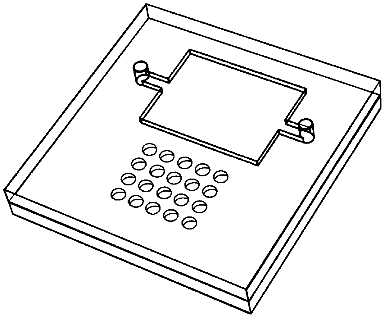
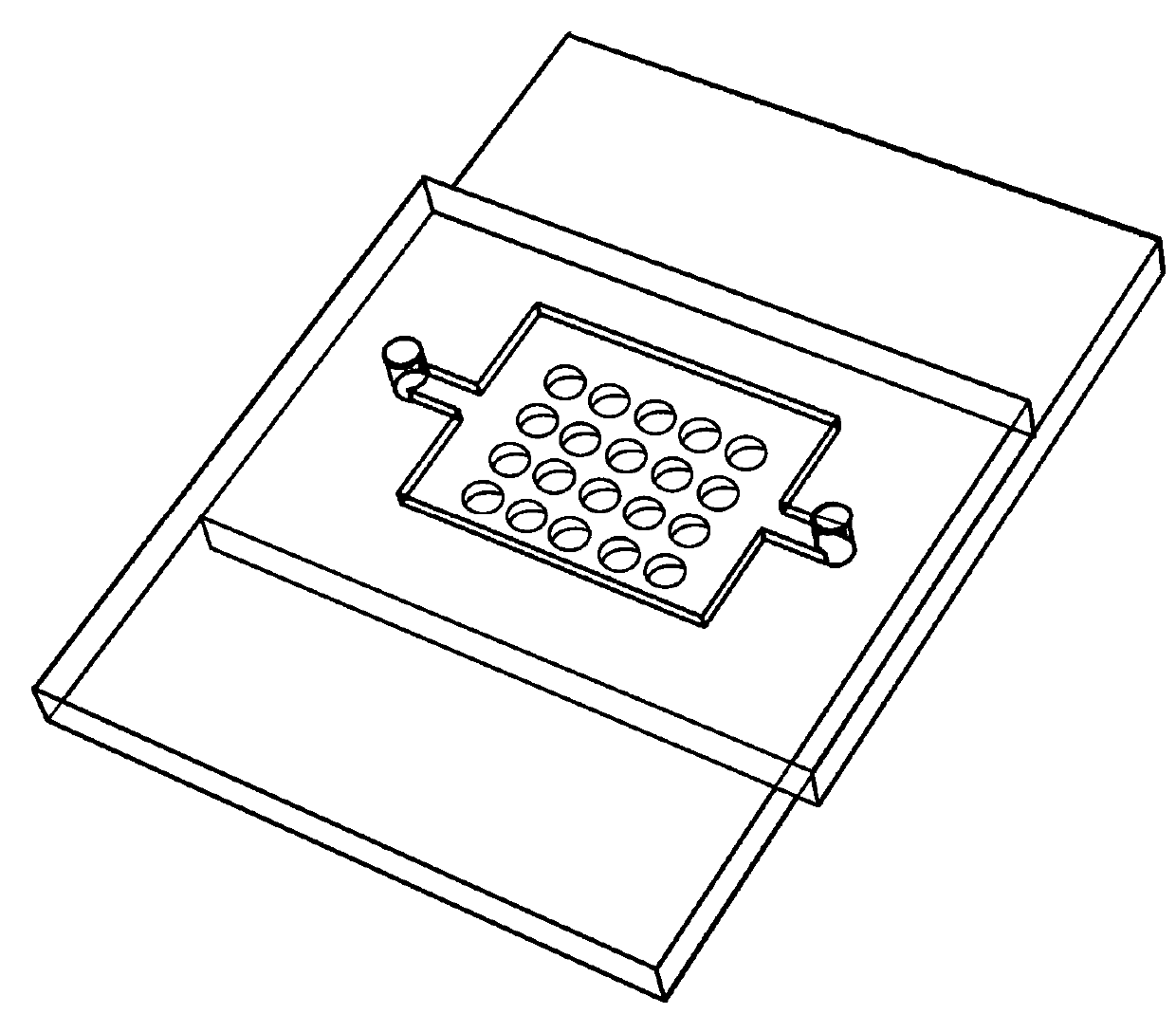
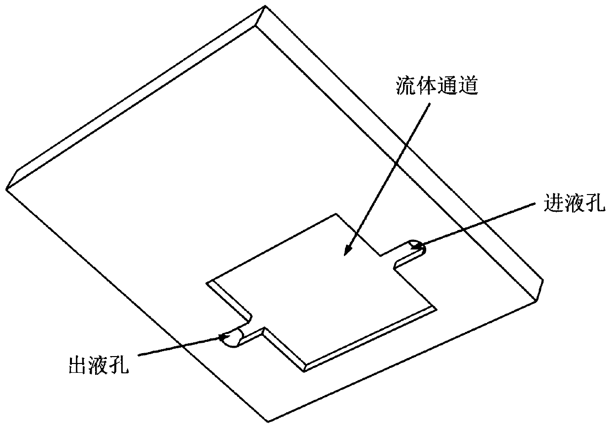
[0040] In this embodiment, an upper chip is prepared on a glass material by a wet etching method (such as image 3 shown) and lower chip (as Figure 4 shown). The fluid channel on the chip has a width of 5 mm, a length of 15 mm, and a depth of 50 microns. The upper chip contains a liquid inlet and a liquid outlet. The lower chip contains 5000 microwells distributed in an area of ​​4.5 mm wide by 12.5 mm long. The etched microholes of the lower chip have a diameter of 80 microns and a depth of 25 microns. The surface of the chip adopts the gas-phase silanization method, and uses dimethyl dichlorosilane to carry out hydrophobic modification treatment on the glass surface. The organic phase components were mineral oil and tetradecane mixed in equal volumes.

[0041] After the upper chip and the lower chip are assembled, a layer of organic phase liquid is added between the upper and lower chips, and the ...

Embodiment 2

[0044] Embodiment 2, digital PCR experiment

[0045] Chip preparation was the same as in Example 1. The upper chip and the lower chip are prepared on the glass material by wet etching. The fluid channel on the chip has a width of 5 mm, a length of 15 mm, and a depth of 50 microns. The upper chip contains a liquid inlet and a liquid outlet. The lower chip contains 5000 microwells distributed in an area of ​​4.5 mm wide by 12.5 mm long. The etched microholes of the lower chip have a diameter of 80 microns and a depth of 25 microns. The surface of the chip adopts the gas-phase silanization method, and uses dimethyl dichlorosilane to carry out hydrophobic modification treatment on the glass surface. The organic phase components were mineral oil and tetradecane mixed in equal volumes. A layer of organic phase liquid is added between the upper and lower chips. When the combination is at the initial position of sample addition, the connected fluid channels of the upper chip and ...


PUM

PropertyMeasurementUnit
widthaaaaaaaaaa
lengthaaaaaaaaaa
depthaaaaaaaaaa

Abstract

The invention discloses a method for generating a liquid droplet array on a microfluidic chip, and relates to the field of liquid droplet generation. The method for generating the liquid droplet arrayon the microfluidic chip includes the following steps that an upper chip and a lower chip are assembled to an initial position, and a fluid pipeline of the upper chip partially or completely covers amicrowell array of the lower chip; a solution is injected into the chip, and the solution partially or completely fills the microwell array of the lower chip; the upper chip and the lower chip are relatively moved to the liquid dividing position, the fluid pipeline of the upper chip and the microwell array of the lower chip no longer overlap, and the solution is dispersed in the microwell array to form the liquid droplet array. The contact surface between the upper chip and the lower chip is hydrophobic, and the microwell array fully physically isolates the generated liquid droplets to avoidcross-contamination. According to the method for generating the liquid droplet array on the microfluidic chip, the device and operation of liquid droplet generation are simplified, the design is flexible, and the size and shape of the generated liquid droplets can be effectively controlled.

Description

technical field [0001] The invention relates to the field of droplet generation, in particular to a method for generating a droplet array on a microfluidic chip. Background technique [0002] Droplets have a wide range of applications in physics, chemistry, biology, and medicine. Among them, a large number (usually more than 100) droplet arrays have shown unique advantages in gene, protein and cell analysis. [0003] Among them, digital PCR gene amplification is a technology based on a large number of independent micro-droplets to accurately quantify the target gene. By dispersing the reaction solution into picoliter or nanoliter microdroplets or reaction microwells, each microdroplet or microwell contains at most one copy of the target gene. For example, some microdroplets or microwells contain a gene of interest and other microdroplets or microwells do not contain the gene of interest. Through the specific amplification of the target gene in the micro-droplet or micro-w...

Claims


Application Information

Patent Timeline
Patent Type & Authority Applications(China)
IPC IPC(8): C12M1/00C12Q1/6851B01L3/00
CPCC12Q1/6851B01L3/5027C12Q2531/113C12Q2563/159B01L3/502738B01L2200/0605B01L2200/0673B01L2300/0887B01L2400/065B01L2300/161B01L2300/0864C12Q2565/629
Inventor 沈峰屈海军吕蔚元迂妍
Owner SHANGHAI JIAOTONG UNIV
Learn More