Cement troweling device for building foundation

A technology of cement and foundation, which is applied in the field of construction, can solve problems such as gaps in automation and coordination, and achieve the effect of improving the effect, avoiding uneven falling, and wide-ranging operations

Inactive Publication Date: 2020-01-03
蔡新新
View PDF0 Cites 6 Cited by
  • Summary
  • Abstract
  • Description
  • Claims
  • Application Information

AI Technical Summary

Problems solved by technology

However, there are certain defects in this patent. There is no operation difference between the cement feeding mechanism and the smoothing mechanism, and there is a gap in the automation cooperation between the two.

Method used


Image

  • Cement troweling device for building foundation
  • Cement troweling device for building foundation
  • Cement troweling device for building foundation

Examples


Embodiment 1

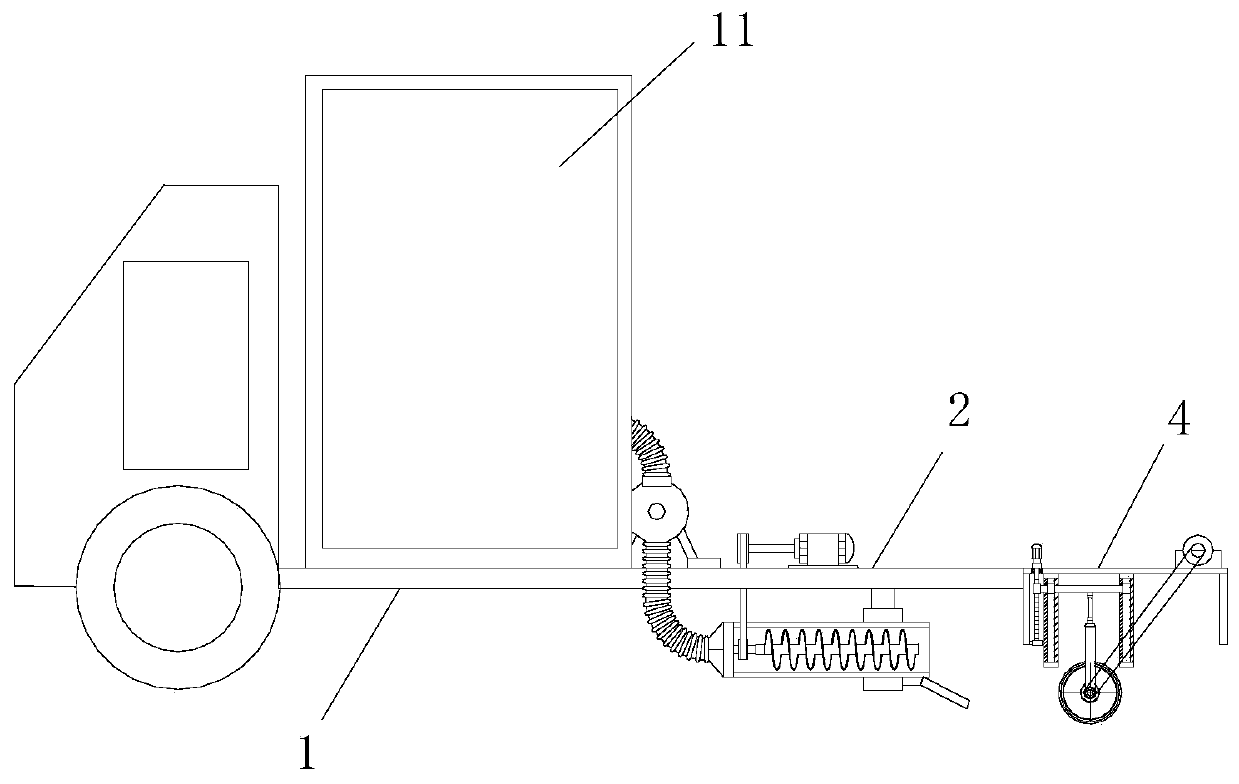
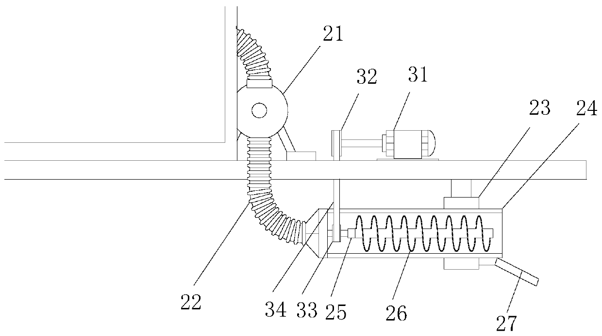
[0028] see figure 1 and figure 2 , a building foundation cement troweling device, comprising a vehicle frame 1, a cement mixing bucket 11 is installed on the vehicle frame 1, and a cement feeding mechanism 2 and a cement troweling mechanism 4 are respectively installed on the vehicle frame 1. The cement feeding mechanism 2 includes a mud pump 21 and a feed frame 23, the feed end of the mud pump 21 is installed at the discharge port of the mixing tank 11, and the feed end of the mud pump 21 is equipped with a feed Conduit 22, described feeding frame 23 is equipped with feeding channel 24, and described feeding conduit 22 is connected with feeding channel 24, and described feeding channel 24 is built-in and installed with feeding roller shaft 25, and described feeding roller shaft 25 is installed with Screw feeding auger 26, a feeding motor 31 is installed on the vehicle frame 1, a drive wheel 32 is installed on the driving end of the feeding motor 31, a driven wheel 33 is ins...

Embodiment 2

[0034] see Figure 5 and Figure 6, this embodiment is a further optimization of Embodiment 1. On the basis of it, a cement pressing mechanism 6 is also provided between the cement feeding mechanism 2 and the cement smoothing mechanism 4, and the cement pressing mechanism 6 is built with a Fixed guide rail 61, described fixed guide rail 61 is built-in and is equipped with movable rod 62, and the bottom end of described movable rod 62 is installed with pressing plate 63, and the top rod end of described movable rod 62 is externally connected with transmission connecting rod 64, and described transmission connecting rod 64, one end is connected with the movable rod 62, and the other end of the transmission link 64 is fixed on the side frame of the cement pressing mechanism 6, and the swinging motor 65 is also installed on the cement pressing mechanism 6, and the swinging motor 65 A swing rod 66 is installed at the driving end of 65, and an arc-shaped groove 67 is arranged on th...


PUM


Abstract

The invention relates to the field related to construction, and particularly discloses a cement troweling device for a building foundation. The cement troweling device for the building foundation comprises a vehicle frame, a cement mixing barrel is mounted on the vehicle frame, a cement feeding mechanism and a cement troweling mechanism are mounted on the vehicle frame respectively, the cement feeding mechanism includes a cement conveying pump and a feeding rack, the feeding rack is provided with a feeding channel, a feeding roller shaft is mounted in the feeding channel in a built-in mode, aspiral feeding auger is mounted on the feeding roller shaft, a lifting frame is mounted in the cement troweling mechanism in a built-in mode, a work frame is mounted at the bottom of the lifting frame, a troweling roller is mounted on the work frame, the lifting frame is externally connected with an outer edge rod, a threaded sleeve is mounted at the rod end of the outer edge rod, a lifting screwis arranged at the side edge of the cement troweling mechanism, and the threaded sleeve is arranged on the lifting screw lifting in threaded fit in a sleeving mode. According to the cement troweling device for the building foundation, uniformity of spreading of cement can be improved, and the cement troweling device for the building foundation adapts to cement foundations of various heights

Description

technical field [0001] The invention relates to related fields of construction, in particular to a construction foundation cement troweling device. Background technique [0002] For the construction of cement pavement, usually the mixer truck mixes the cement, dumps it on the road surface of the road, and then divides the cement on the road surface manually. The ground is smoothed. At present, the ground is generally smoothed manually and by a troweling machine. Manually smoothing the cement floor is time-consuming and laborious, and the smoothing efficiency is low. Long-term work will also bring greater labor intensity to the staff. [0003] Chinese patent (authorization announcement number: CN 08486152U) has announced a kind of cement floor smoothing device for building, can carry out smoothing operation to cement automatically by mud smoothing mechanism. But there is certain defect in this patent, there is no operation difference between cement feeding mechanism and trow...

Claims


Application Information

Patent Timeline
Patent Type & Authority Applications(China)
IPC IPC(8): E01C19/48
CPCE01C19/4866
Inventor 蔡新新
Owner 蔡新新
Why Eureka
Try Eureka