Casing-through induction logging method based on lateral wave detection

A technology of induction logging and casing passing, which is used in surveying, earth-moving drilling, wellbore/well components, etc., can solve problems such as poor measurement results, achieve good results, reduce primary field interference, and improve signal-to-noise ratio Effect

Active Publication Date: 2020-01-03
ZHEJIANG UNIV
View PDF9 Cites 1 Cited by
  • Summary
  • Abstract
  • Description
  • Claims
  • Application Information

AI Technical Summary

Problems solved by technology

The measurement coil of this method does not need to contact the inner wall of the casing, which eliminates the problem of poor measure

Method used


Image

  • Casing-through induction logging method based on lateral wave detection
  • Casing-through induction logging method based on lateral wave detection
  • Casing-through induction logging method based on lateral wave detection

Examples


Embodiment 1

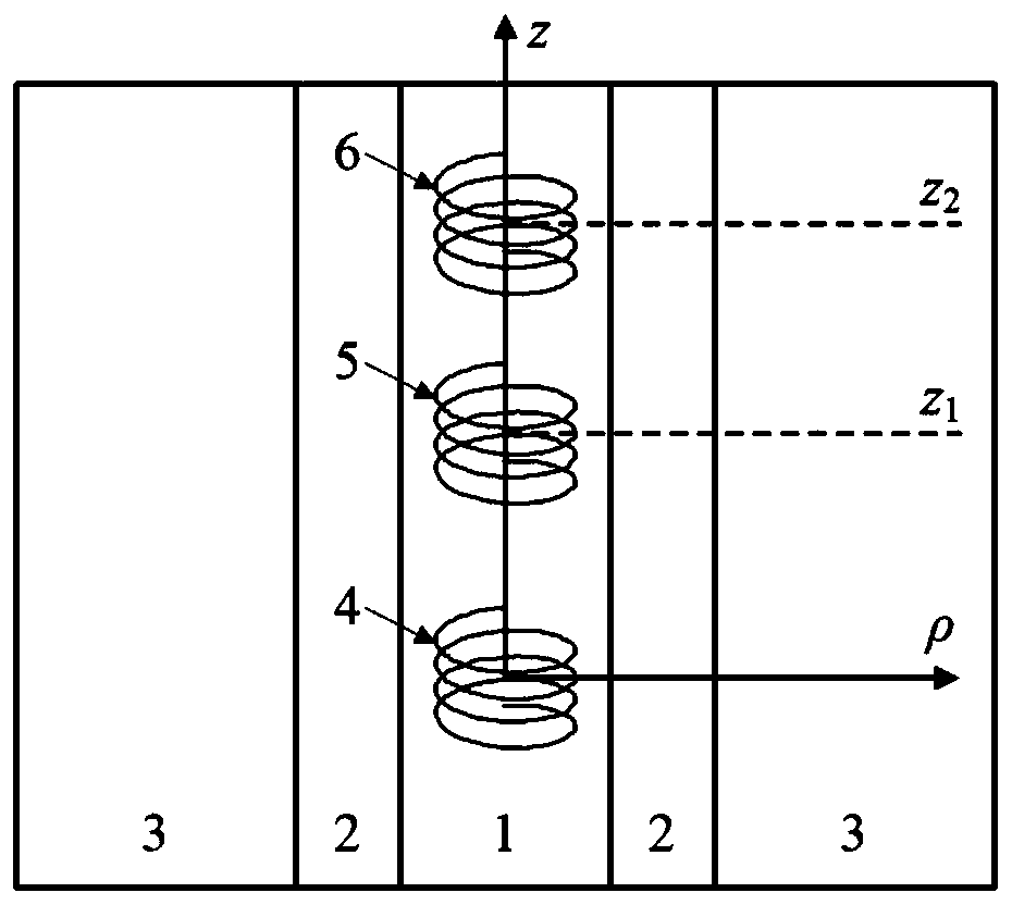
[0043] 1) if figure 1 As shown, the detection device is arranged in the cased well 1. The detection device includes a transmitting coil 4 and two main receiving coils 5 and 6. The coil winding directions of the transmitting coil 4 and the two main receiving coils 5 and 6 are the same, and the two main receiving coils The receiving coils 5 and 6 and the transmitting coil 4 are coaxially arranged up and down in the cased well respectively, and the transmitting coil 2 is located below the two main receiving coils 3, and the transmitting coil 4 is excited by a sine wave current, in the inside 1 and outside 3 of the cased well Generate an induced electromagnetic field and use the main receiving coils 5 and 6 to measure the magnetic field inside the cased hole;

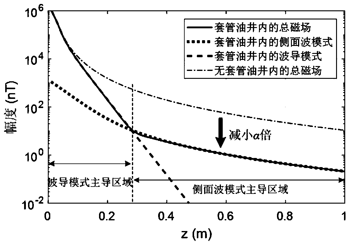
[0044] Wherein, the main receiving coils 5 and 6 are arranged in the dominant area of ​​the side wave mode of the induced electromagnetic field generated by the transmitting coil 4 . The side wave mode dominant area means...

Embodiment 2

[0069] In the side-wave dominant area, the magnetic field distribution in the well is the same as that in the uncased well, but the amplitude is weakened by α times. Therefore, similar to open hole logging, the interference of the primary field can be weakened by using the reverse winding compensating receiving coil.

[0070] The specific method is as follows: Figure 5 As shown, the detection device is arranged in the cased well 1, and the detection device includes a transmitting coil 4, two main receiving coils 5 and 6 and two compensating receiving coils 7 and 8, two compensating receiving coils, two main receiving coils and The transmitting coils are coaxially arranged up and down in the cased well respectively, and the transmitting coil 4 is excited by a sine wave current to generate an induced electromagnetic field inside 1 and outside 3 of the cased well. The number of turns of the compensation receiving coil 7 is proportional to the induced voltage generated by the tr...


PUM


Abstract

The invention discloses a casing-through induction logging method based on lateral wave detection. The casing-through induction logging method comprises the following steps of arranging a detection device in a cased well, wherein the detection device comprises a transmitting coil, two main receiving coils and two compensation receiving coils, the two main receiving coils, the two compensation receiving coils and the transmitting coil are respectively arranged in the cased well vertically and coaxially; exciting the transmitting coil by sine wave currents to generate induction electromagnetic fields inside and outside the cased well; using the main receiving coils to measure magnetic fields of a plurality of different positions inside the cased well; collecting the ratio of the magnetic field measurement results of the two main receiving coils at different axial positions in the cased well; and inputting the ratio into an inversion model of the transmitting coil in a caseless well to obtain the formation conductivity. According to the casing-through induction logging method based on lateral wave detection, the measuring coils does not need to contact the inner wall of a casting, sothat the problems of poor measuring effect and the like caused by poor contact under the condition of serious casting corrosion of a casting-through logging instrument based on the electrode method are solved.

Description

technical field [0001] The invention relates to the technical field of geophysical detection in wells, in particular to a through-casing logging device and method for exciting and measuring electromagnetic fields in oil and gas wells with metal casings, thereby obtaining the distribution information of the conductivity of formations around the wells. Background technique [0002] In the petroleum industry, measuring the electrical conductivity of the formation outside the well inside the oil well is an important means of evaluating the remaining oil. However, there are metal casings in most production wells, which makes the conductivity logging through the casing very difficult. [0003] The realization of the conductivity measurement through the casing can be divided into two types: the electrode method and the induction method. The electrode method injects quasi-static current into the casing and the formation through the measuring electrode. Since the conductivity of the...

Claims


Application Information

Patent Timeline
IPC IPC(8): E21B47/00E21B49/00
CPCE21B47/00E21B49/00
Inventor 申发中冉立新
Owner ZHEJIANG UNIV
Why Eureka
Try Eureka