A translation push-pull hob tool system and tool changing method
A cutting tool system and hob technology, which is applied in earthwork drilling, mining equipment, tunnels, etc., can solve the problems of poor cooperation and low automation of tool changing robots, and achieve the reduction of the risk of manual tool changing and high automation , the effect of high coordination
- Summary
- Abstract
- Description
- Claims
- Application Information
AI Technical Summary
Problems solved by technology
Method used
Image
Examples
Embodiment 1
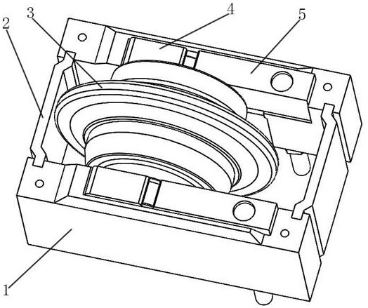
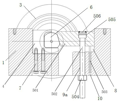
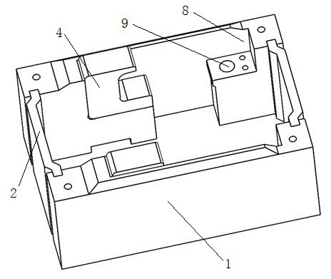
[0027] Example 1, such as figure 1 As shown, a translation push-pull hob cutter system includes a cutter box 1 and a hob 3, and the hob is located in the cutter box and is detachably connected to the cutter box. The inner walls on both sides of the knife box 1 are provided with a block 4 and a translation push-pull locking mechanism 5 for clamping the hob cutter shaft 6. The block 4 corresponds to the translation push-pull locking mechanism 5. When installing, the hob The cutter shaft is located between the block and the translational push-pull locking mechanism, and whether the hob cutter shaft is pressed or not is realized through the up and down translation movement of the translational push-pull locking mechanism. Both ends of the knife box 1 are clamped with connecting plates 2, and the connecting plate 2 is detachably connected with the knife box 1 to realize the sealing of the knife box.
[0028] Further, the clamping block 4 is fixedly connected with the cutter box 1 ...
Embodiment 2
[0031] Example 2, such as figure 2 As shown, a translation push-pull hob tool system, the mounting hole 9 is a threaded hole 9a matched with the threaded rod 502, the threaded rod 502 is threaded with the threaded hole 9a, the tool changing robot rotates the lock nut, and the lock nut Drive the threaded rod to rotate along the threaded hole, and drive the translation pressing block to move up and down. The bottom of the mounting groove 8 is provided with a vertically arranged guide hole 10 . The bottom of the translation briquetting block 501 is fixedly provided with a guide rod 503, the guide rod 503 cooperates with the guide hole 10, the translation briquetting block moves up and down, and the guide rod moves up and down in the guide hole to ensure that the translation briquetting block moves up and down in translation, ensuring translation The briquetting movement is precise.
[0032] Other structures are the same as in Embodiment 1.
[0033] The tool change method of t...
Embodiment 3
[0035] Example 3, such as Figure 6~7As shown, a translation push-pull hob tool system, the installation hole 9 is a vertical waist hole 9b, the threaded rod 502 passes through the vertical waist hole 9b and can move left and right in the vertical waist hole 9b, and the tool changing robot pushes The threaded rod moves in the vertical waist hole to realize the left and right movement of the translation pressing block. Other structures are the same as in Embodiment 1.
[0036] The tool change method of the above-mentioned translational push-pull hob tool system includes the following steps: ①Tool disassembly: the tool changer of the tool changer robot clamps the lock nut 504, turns the lock nut 504 counterclockwise, and the threaded rod 502 moves upward to press the lock nut 504. The block 501 is pushed out of the installation groove 8, and at this moment, the translation pressing block 501 is separated from the hob cutter shaft 6; 3. Take out to let out the channel, and then...
PUM
 Abstract
Description
Claims
Application Information
 - R&D
- Intellectual Property
- Life Sciences
- Materials
- Tech Scout
- Unparalleled Data Quality
- Higher Quality Content
- 60% Fewer Hallucinations
Browse by: Latest US Patents, China's latest patents, Technical Efficacy Thesaurus, Application Domain, Technology Topic, Popular Technical Reports.
© 2025 PatSnap. All rights reserved.Legal|Privacy policy|Modern Slavery Act Transparency Statement|Sitemap|About US| Contact US: help@patsnap.com


