
Rotary regulating mechanism

A technology of rotating adjustment and adjusting rod, applied in the directions of cameras, supporting machines, mechanical equipment, etc., can solve the problems of complex adjustment mechanism structure, poor stability of up-down adjustment and left-right adjustment, and low adjustment accuracy.

Pending Publication Date: 2020-01-03
湖南讯目科技有限公司
View PDF1 Cites 2 Cited by
  • Summary
  • Abstract
  • Description
  • Claims
  • Application Information

AI Technical Summary

Problems solved by technology

[0008] The adjustment mechanism disclosed in this patent document has a complex structure, low adjustment accuracy, and poor stability in its up-down adjustment and left-right adjustment.

Method used


Image

  • Rotary regulating mechanism
  • Rotary regulating mechanism
  • Rotary regulating mechanism

Examples


Embodiment Construction

[0032]The following will clearly and completely describe the technical solutions in the embodiments of the present invention with reference to the accompanying drawings in the embodiments of the present invention. Obviously, the described embodiments are only part of the embodiments of the present invention, not all of them. Based on the embodiments of the present invention, all other embodiments obtained by persons of ordinary skill in the art without creative efforts fall within the protection scope of the present invention.

[0033] It should be noted that all directional indications (such as up, down, left, right, front, back...) in the embodiments of the present invention are only used to explain the relationship between the components in a certain posture (as shown in the accompanying drawings). Relative positional relationship, movement conditions, etc., if the specific posture changes, the directional indication will also change accordingly.

[0034] In addition, in th...


PUM


Abstract

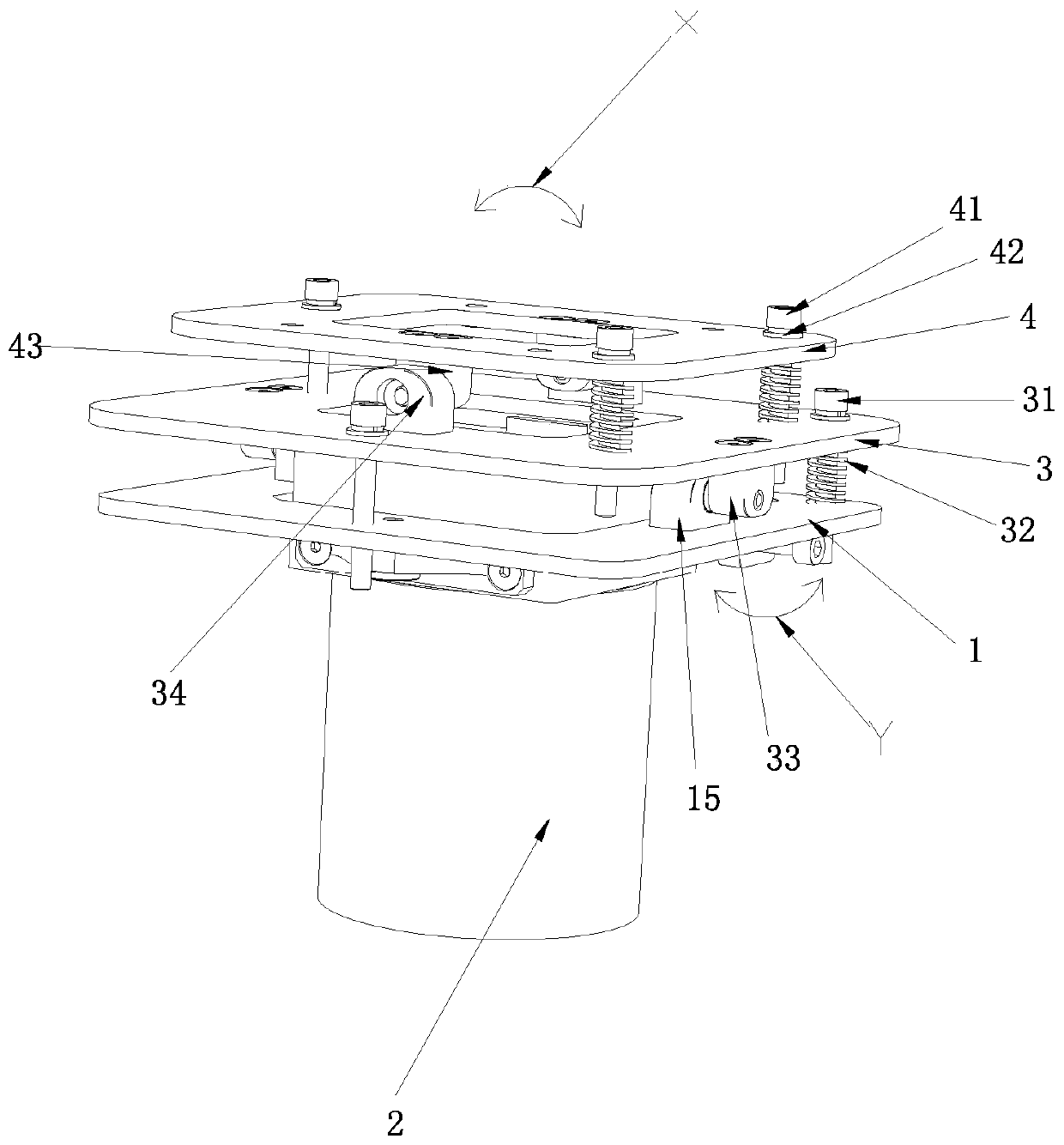
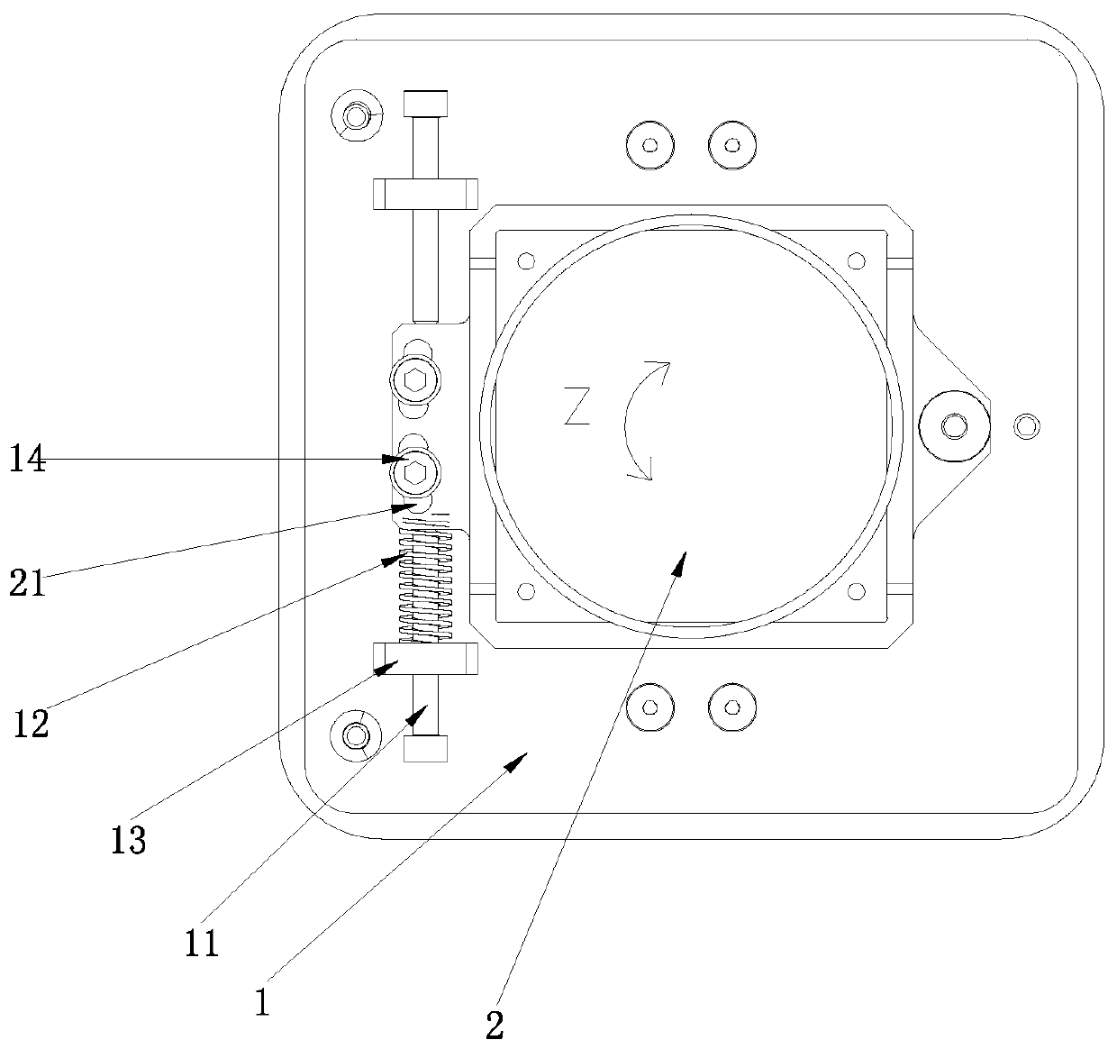
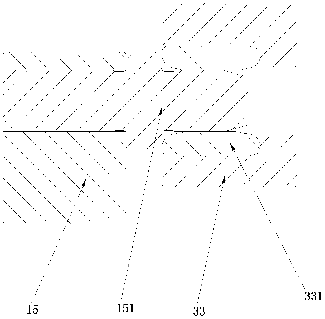
The invention discloses a rotary regulating mechanism, and is applied to the field of regulating machines. The rotary regulating mechanism comprises a first bottom plate and working equipment; the first bottom plate is movably provided with two opposite first regulating rods; each of the two first regulating rods has a stroke that the regulating rods move in the axial direction of the first bottomplate; one end of the working equipment is rotatably arranged on the first bottom plate; the other end of the working equipment is connected between the two first regulating rods; at least one of thefirst regulating rods is sleeved with a first elastic component; and the at least one first elastic component is arranged between the corresponding first regulating rod and the working equipment in an abutted manner. The rotary regulating mechanism is simple in structure, high in regulating precision and high in stability.

Description

technical field [0001] The invention belongs to the field of adjusting machinery, and in particular relates to a rotation adjusting mechanism. Background technique [0002] The camera is the core component of the machine vision system. The installation accuracy and stability of the camera directly determine the quality of image acquisition, which is very critical for data post-processing. Due to the inevitable position and angle errors introduced in the manufacturing and assembly process of the working platform or system, multi-dimensional precise adjustment is required after the initial installation of the camera. Since the machine vision system is particularly sensitive to the position and angle of the camera, this requires the adjustment mechanism to have the characteristics of high precision, good stability, and no inter-axis coupling. [0003] The patent document with the application number CN201710158821 discloses a CCD camera adjustment mechanism, which includes a CC...

Claims


Application Information

Patent Timeline
Patent Type & Authority Applications(China)
IPC IPC(8): F16M11/12F16M11/16G03B17/56
CPCF16M11/121F16M11/16G03B17/561F16M2200/041
Inventor 汤美林王罡彭灿梁迅
Owner 湖南讯目科技有限公司
Learn More