Eureka AIR delivers breakthrough ideas for toughest innovation challenges, trusted by R&D personnel around the world.

Cutter head wear detection device for shield machine

A detection device and shield machine technology, which is applied in the field of shield machines, can solve problems such as increasing structural installation space and economic costs, entering shutdown, entering warehouse inspection, and reducing pressure, so as to ensure safety and stability, and save energy. Space and cost, the effect of compact installation structure

Pending Publication Date: 2020-01-03
XCMG KAIGONG HEAVY IND NANJING
View PDF0 Cites 1 Cited by
  • Summary
  • Abstract
  • Description
  • Claims
  • Application Information

AI Technical Summary

Problems solved by technology

However, the disadvantages of this existing structure are as follows: 1) In order to ensure that the cutter head wear detection device can work normally, it is necessary to add an oil passage rotary joint at the end of the central rotating body to supply pressure oil to the detection device, which increases the installation space of the structure and Economic cost; 2) When the hydraulic oil passes through the hydraulic rotary joint or other structural parts, due to the failure of the seal of the joint or the failure of the end face seal ring of the structural part, the hydraulic oil will leak, resulting in a decrease in the pressure on the oil circuit, and a false alarm from the pressure sensor, which will cause the machine to Enter a series of procedures such as shutdown and warehouse inspection, which will affect the progress of the entire shield machine; 3) After the detection hole is worn out or the sealing ring fails, hydraulic oil leakage will cause water and soil pollution in the tunnel and construction costs increase

Method used


Image

  • Cutter head wear detection device for shield machine

Examples


Embodiment Construction

[0020] Hereinafter, a preferred embodiment of the present invention will be described in detail with reference to the accompanying drawings.

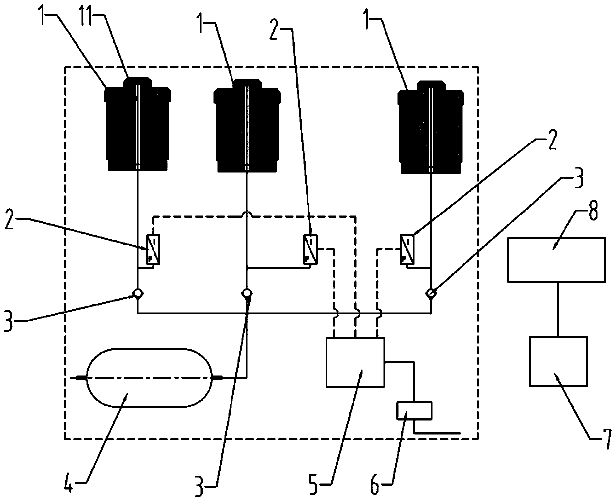
[0021] Refer to figure 1 , Is a cutter head wear detection device for shield machine according to the present invention, including a detection head 1, a pressure sensor 2, a one-way 3, a gas cylinder 4, a signal transmitter 5, a conductive slip ring 6 and a signal receiver 7 .

[0022] The detection head 1 is a steel workpiece, and a detection hole 11 is machined inside, and the detection hole is a blind hole. The detection head 1 is welded to the cutter head panel or the circumference of the cutter head, and multiple detection heads 1 can be welded according to actual conditions.

[0023] The gas cylinder 4 is fixed near the flange of the cutter head of the shield machine. The gas cylinder 4 is filled with compressed air. The open end of the detection hole of each detection head 1 is connected to the gas cylinder 4 through a pipeline. Duri...


PUM


Abstract

The present invention discloses a cutter head wear detection device for a shield machine. The cutter head wear detection device comprises a detection head, a pressure sensor, a check valve, a gas cylinder, a signal transmitter, a conductive slip ring and a signal receiver; the detection head is internally provided with a detection hole; the detection hole is connected with the gas cylinder through a pipeline; the connection pipeline between the detection head and the gas cylinder is provided with the check valve and the pressure sensor; and the pressure sensor is configured to check the pressure on the connection pipeline and transmit the pressure to a controller of the shield machine through the signal transmitter and the signal receiver. According to the cutter head wear detection device for the shield machine provided by the present invention, the pressure signal can be automatically detected when the detection hole is worn, the pressure signal can be wirelessly transmitted to thecontroller, and a shield machine operation program is locked, so that the machine is unable to continue digging, and the safety and stability of the cutter head structure of the shield machine are ensured; the compressed air is used for detection, and the compressed air will not pollute the water and soil in the tunnel after the detection hole is worn through; and the cutter head wear detection device for the shield machine has no hydraulic rotary joint, and has a compact installation structure for convenient installation, so that the space and the cost are saved.

Description

Technical field [0001] The invention belongs to the technical field of shield machines, and specifically relates to a cutter head wear detection device for shield machines. Background technique [0002] In order to ensure that the shield machine can monitor the wear of the tool or panel during the tunneling process, a wear detection device is generally designed on the cutter head; under normal circumstances, there are 2 to 4 wear detection devices on the cutter head, and their main functions are as follows: 1) The cutter head circumferential direction wear detection device mainly monitors the wear of the cutter head circumferential direction tools and related structural parts; 2) The cutter head panel wear detection device mainly monitors the wear of the tools on the cutter head panel and the wear of the cutter head panel itself. [0003] The working principle of the existing cutter head wear detection device is as follows: the detection device is integrally welded to the cutter he...

Claims


Application Information

Patent Timeline
IPC IPC(8): G01B13/00G01D5/42
CPCG01B13/00G01D5/42
Inventor 苏延奇徐昊朗李留涛姚强生
Owner XCMG KAIGONG HEAVY IND NANJING
Why Eureka
Eureka Blog
Learn More