Eureka AIR delivers breakthrough ideas for toughest innovation challenges, trusted by R&D personnel around the world.

A production process for the insulation of exposed wire ends of lithium battery wires

A production process and lithium battery technology, applied in the direction of circuits, electrical components, circuit/collector components, etc., can solve problems such as unsuitable tightness, influence on welding process, moisture oxidation of exposed wire ends, etc., and achieve good moisture resistance Oxidation effect, reduce labor cost, and solve the effect of moisture oxidation problem

Active Publication Date: 2021-07-23
HUIZHOU HENGTAI TECH
View PDF4 Cites 0 Cited by
  • Summary
  • Abstract
  • Description
  • Claims
  • Application Information

AI Technical Summary

Problems solved by technology

[0003] However, when insulating tape is used to attach and cover the exposed wire ends, there will be exposed glue around the insulating tape, which will cause multiple wires to stick to each other, which will easily cause wire confusion, which will cause wire quality problems and increase production man-hours; When the insulating tape is removed during processing, there will be residual glue left on the exposed wire ends, which will affect the subsequent welding process and lead to poor tin eating
[0004] Furthermore, in the prior art, the tightness of the sleeve to the exposed wire ends of the wires cannot reach an appropriate level at all. If the sleeves are loose to the exposed wire ends of the wires, the sleeves will easily fall off from the exposed wire ends, resulting in failure of its insulation function. ; If the sleeve is tight to the exposed wire end of the wire, it is difficult for the exposed wire end to penetrate into the sleeve, the processing time is too long, and the efficiency is too low; Into the gap between the exposed thread and the exposed thread, so that the exposed thread is oxidized by moisture, resulting in quality problems such as poor tin eating of the exposed thread

Method used


Image

  • A production process for the insulation of exposed wire ends of lithium battery wires
  • A production process for the insulation of exposed wire ends of lithium battery wires
  • A production process for the insulation of exposed wire ends of lithium battery wires

Examples


Embodiment approach

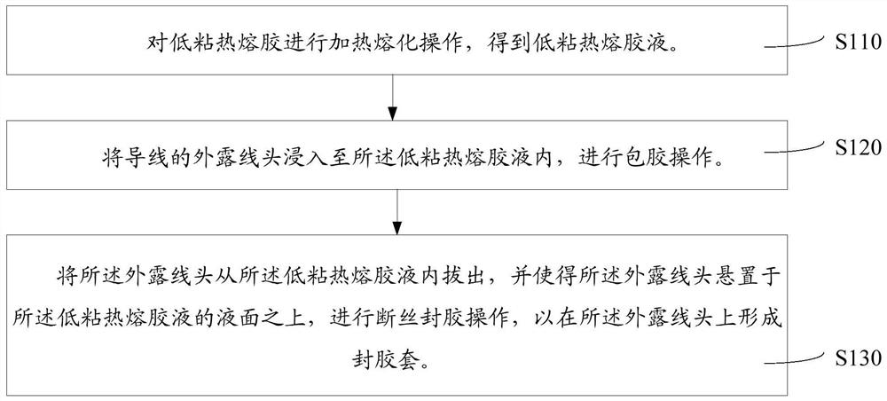
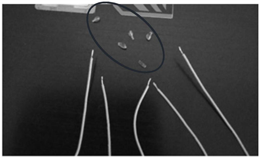
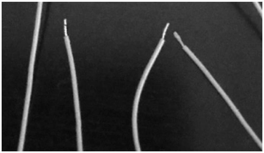
[0034] In order to better describe the above-mentioned production process for the exposed wire end insulation of lithium battery wires, to better understand the concept of the above-mentioned production process for the exposed wire end insulation of lithium battery wires. For an implementation, see figure 1 , a lithium battery lead wire exposed end insulation production process, comprising the following steps: S110, performing a heating and melting operation on the low-viscosity hot-melt adhesive to obtain a low-viscosity hot-melt adhesive liquid. S120, immersing the exposed wire ends of the wires into the low-viscosity hot-melt glue liquid, and performing the encapsulation operation. S130, pulling out the exposed thread ends from the low-viscosity hot-melt adhesive liquid, and suspending the exposed thread ends above the liquid surface of the low-viscosity hot-melt adhesive liquid, and performing a broken wire sealing operation, to form a sealing sleeve on the exposed wire e...

Embodiment 1

[0063] S111, at a temperature of 160°C, stir 10 parts of polyurethane resin, 40 parts of polysulfide rubber, 3 parts of antioxidant 1010, 1 part of diphenylguanidine, 2 parts of zinc peroxide, 60 parts of methanol and 10 parts of paraffin Operation, so that the components are mixed uniformly to obtain a low-viscosity hot-melt adhesive, and the low-viscosity hot-melt adhesive is heated and melted so that the temperature of the low-viscosity hot-melt adhesive reaches 160°C to obtain a low-viscosity hot-melt adhesive.

[0064] S121, immersing the exposed wire ends of the wires into the low-viscosity hot-melt adhesive liquid for 1 second, and performing the encapsulation operation.

[0065] S131, pull out the exposed thread end from the low-viscosity hot-melt adhesive liquid, and make the exposed thread end suspend at a distance of 3 mm above the liquid surface of the low-viscosity hot-melt adhesive liquid to stay for 1 second, and carry out Sealing of broken wires to form a seali...

Embodiment 2

[0067] S112, under the temperature condition of 220 ℃, for 20 parts of polyurethane resin, 20 parts of polysulfide rubber, 10 parts of antioxidant TNP, 0.5 parts of tetramethylthiuram monosulfide, 4 parts of lead dioxide, 40 parts of toluene and Stir 20 parts of paraffin to mix the components evenly to obtain low-viscosity hot-melt adhesive. Heat and melt the low-viscosity hot-melt adhesive so that the temperature of the low-viscosity hot-melt adhesive reaches 220°C to obtain low-viscosity hot-melt adhesive. Melt glue.

[0068] S122, immersing the exposed end of the wire into the low-viscosity hot-melt glue liquid for 2 seconds, and performing a glue-covering operation.

[0069] S132, pull out the exposed thread end from the low-viscosity hot-melt adhesive liquid, and make the exposed thread end suspend at a distance of 2 mm above the liquid surface of the low-viscosity hot-melt adhesive liquid for 2 seconds, and perform Sealing of broken wires to form a sealing sleeve on the...


PUM


Abstract

The invention relates to the field of wire head insulation treatment technology, and discloses a lithium battery lead wire exposed wire end insulation production process, comprising the following steps: performing a heating and melting operation on a low-viscosity hot-melt adhesive to obtain a low-viscosity hot-melt adhesive liquid; Dip into the low-viscosity hot-melt adhesive liquid, and carry out encapsulation operation; pull out the exposed wire end from the low-viscosity hot-melt adhesive liquid, and make the exposed thread end hang on the low-viscosity hot-melt adhesive Above the liquid level of the glue, seal the broken wire to form a seal sleeve on the exposed thread end. The invention uses low-viscosity hot-melt adhesive to form a sealing rubber sleeve on the exposed wire end, the insulation operation is simple and convenient, it is not easy to produce residual glue, and the exposed wire end has good sealing and covering performance, which solves the short circuit problem of the exposed wire end of the wire and solves the problem of the exposed wire end Oxidation due to moisture, so that the tin-eating effect of exposed wire ends is good. The cost of low-viscosity hot melt adhesive is far lower than the cost of insulating tape and sleeve, which can increase the production efficiency by more than 300%.

Description

technical field [0001] The invention relates to the field of wire end insulation treatment technology, in particular to a production process for the insulation of exposed wire ends of lithium battery wires. Background technique [0002] For the exposed wire end of the wire, in order to prevent it from being oxidized by the air, it needs to be insulated. Generally, an insulating tape or a sleeve is attached to cover or cover the exposed wire end to ensure that it can achieve the insulation function. For example, in the lithium battery industry, after the lithium battery and the protection board are assembled, the exposed wire ends of the wires on the protection board need to ensure their insulation function, so as to avoid the problem of direct electrical connection between the exposed wire ends and foreign objects or adjacent wire ends. Avoid short circuit problems. For example, in the wire industry, during the process of product processing until the product is packed and s...

Claims


Application Information

Patent Timeline
Patent Type & Authority Patents(China)
IPC IPC(8): H01R43/18H01R43/00C09J181/04C09J175/04C09J191/06C09J11/04C09J11/06
CPCC08K2003/2234C08K2003/2262C08K2003/2296C09J11/04C09J11/06C09J175/04C09J181/04C09J191/06H01R43/005H01R43/18C08L75/04C08L91/06C08K3/22C08K5/31C08L81/04C08K5/40C08K13/02C08K3/06C08K5/47
Inventor 杜智雄黄锐升李路强曾贤华
Owner HUIZHOU HENGTAI TECH
Why Eureka
Eureka Blog
Learn More