Leaking stoppage device

A technology of plugging and leaking rods, which is applied in the field of plugging devices and can solve problems such as the inability to immediately cut off the communication between the mold and the molten metal in the crucible

Pending Publication Date: 2020-01-07
GUANGDONG UNIV OF TECH
View PDF0 Cites 0 Cited by
  • Summary
  • Abstract
  • Description
  • Claims
  • Application Information

AI Technical Summary

Problems solved by technology

[0004] In view of this, the purpose of this application is to provide a leak-stopping device, which effectively solves the technical problem in the prior art that the connection between the mold and the molte

Method used


Image

  • Leaking stoppage device
  • Leaking stoppage device
  • Leaking stoppage device

Examples


Embodiment 1

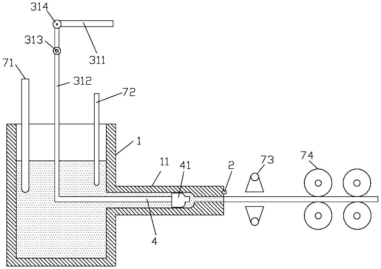
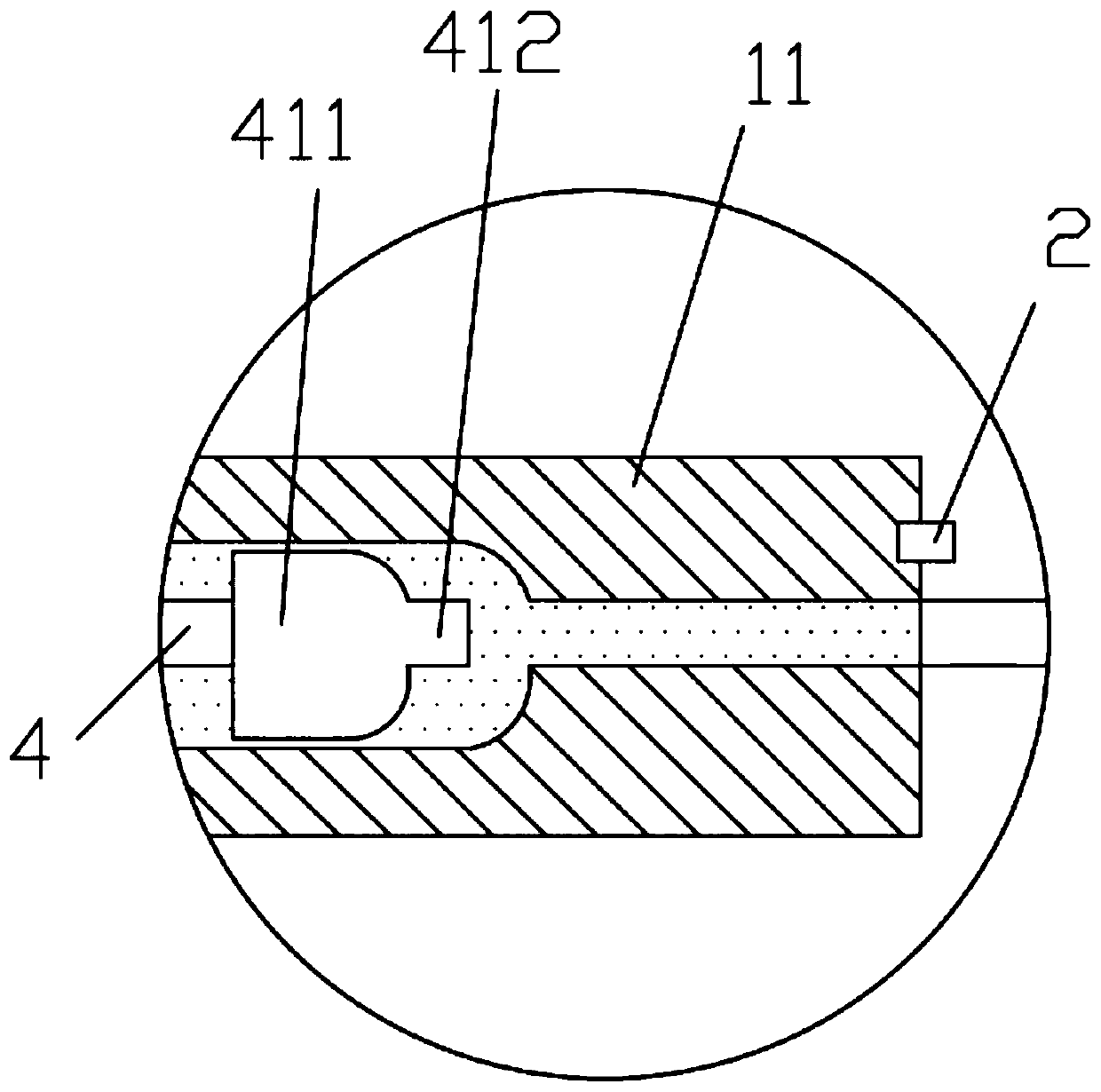
[0031] Please refer to figure 1 , the application provides a kind of embodiment, and this embodiment comprises box body 1, temperature sensor 2, controller, driver 3 and plugging rod 4; Box body 1 is provided with drain pipe 11, and the liquid inlet of drain pipe 11 The mouth is located on the side wall of the box body 1, and the plugging rod 4 is arranged inside the drain pipe 11, and the leak plugging rod 4 is provided with a plug 41 matching the liquid outlet of the drain pipe 11; the temperature sensor 2 is arranged on the The periphery of the liquid outlet of the discharge pipe 11; the temperature sensor 2 is connected with the controller, and the controller is connected with the driver 3; the driver 3 is provided with a driving rod 31, and the driving rod 31 is connected with the plugging rod 4; When the temperature value is greater than the set value of the controller, the controller controls the driver 3 to drive the driving rod 31 to drive the plugging rod 4, so that ...

Embodiment 2

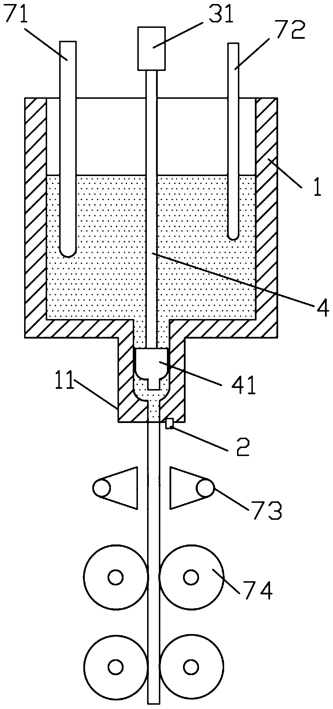
[0046] Please refer to image 3 , the application also provides another embodiment, the present embodiment includes a casing 1, a temperature sensor 2, a controller, a driver 3 and a plugging rod 4; the casing 1 is provided with a drain pipe 11, the drain pipe 11 The liquid inlet is located on the bottom wall of the box body 1, and the plugging rod 4 is arranged inside the drain pipe 11, and the leak plugging rod 4 is provided with a plug 41 matching the liquid outlet of the drain pipe 11; the temperature sensor 2 Set on the periphery of the liquid outlet of the discharge pipe 11; the temperature sensor 2 is connected to the controller, and the controller is connected to the driver 3; the driver 3 is provided with a driving rod 31, and the driving rod 31 is connected to the plugging rod 4; when the temperature sensor 2 When the detected temperature value is greater than the preset temperature of the controller, the controller controls the driver 3 to drive the driving rod 31 t...


PUM


Abstract

The invention relates to the technical field of leaking stoppage, in particular to a leaking stoppage device. The device comprises a box body, a temperature sensor, a controller, a driver and a leaking stoppage rod. The box body is provided with a liquid draining pipe, the leaking stoppage rod is arranged in the liquid draining pipe, the leaking stoppage rod is provided with a leaking stoppage plug matched with a liquid outlet of the liquid draining pipe, the temperature sensor is arranged on the periphery of the liquid outlet of the liquid draining pipe, and is connected with the controller,the controller is connected with the driver, the driver is provided with a driving rod, the driving rod is connected with the leaking stoppage rod, when the temperature value detected by the temperature sensor is larger than the set value of the controller, the controller controls the driver to drive the driving rod so as to drive the leaking stoppage rod, and the leaking stoppage plug plugs the liquid outlet of the liquid draining pipe from the interior of the liquid draining pipe. The technical problems that in the prior art, when breaking out happens, communication of a casting mold and molten metal in a crucible cannot be cut off immediately is effectively solved, during breaking out, the liquid outlet can be plugged in time, the waste of the molten metal is reduced, and the safety accidents are avoided.

Description

technical field [0001] The present application relates to the technical field of leak plugging, in particular to a leak plugging device. Background technique [0002] Hot-type continuous casting technology is a near-net-shape manufacturing technology that can achieve directional solidification. Its mold is not cooled, but heated to keep the molten metal in a liquid state. Cooling by the cooling water device outside the mold outlet, the solid-liquid interface of the metal liquid cooling is near the mold outlet, which can make the casting surface quality good and can produce directional solidified columnar crystal or single crystal structure. The position of the solid-liquid interface is related to the distance from the cooling water to the mold outlet, the temperature of the mold outlet, and the casting speed. When the process parameters are unreasonable and the solid-liquid interface moves to a certain distance outside the mold outlet, the surface tension of the molten met...

Claims


Application Information

Patent Timeline
IPC IPC(8): B22D11/04B22D11/18
CPCB22D11/04B22D11/182
Inventor 王果肖小亭邓俊黎沃光余业球
Owner GUANGDONG UNIV OF TECH
Why Eureka
Try Eureka