Sand blasting process applied to environment-friendly box variable shell

An environmental protection box and sandblasting technology, which is applied in the direction of manufacturing tools, metal processing equipment, abrasive feeding devices, etc., can solve the problems of large unevenness, etc., and achieve the effect of smooth construction surface, convenient use, and reduced coating thickness

Inactive Publication Date: 2020-01-07
CHONGQING WANGBIAN ELECTRIC GRP CORP
View PDF6 Cites 1 Cited by
  • Summary
  • Abstract
  • Description
  • Claims
  • Application Information

AI Technical Summary

Problems solved by technology

[0003] The present invention intends to provide a sand blasting process applied to the shell of the environmental protection box to solve the technical problem that the existing technology is easy to cause a large difference in unevenness when the manual method is used for roughening

Method used


Image

  • Sand blasting process applied to environment-friendly box variable shell
  • Sand blasting process applied to environment-friendly box variable shell
  • Sand blasting process applied to environment-friendly box variable shell

Examples


Embodiment 1

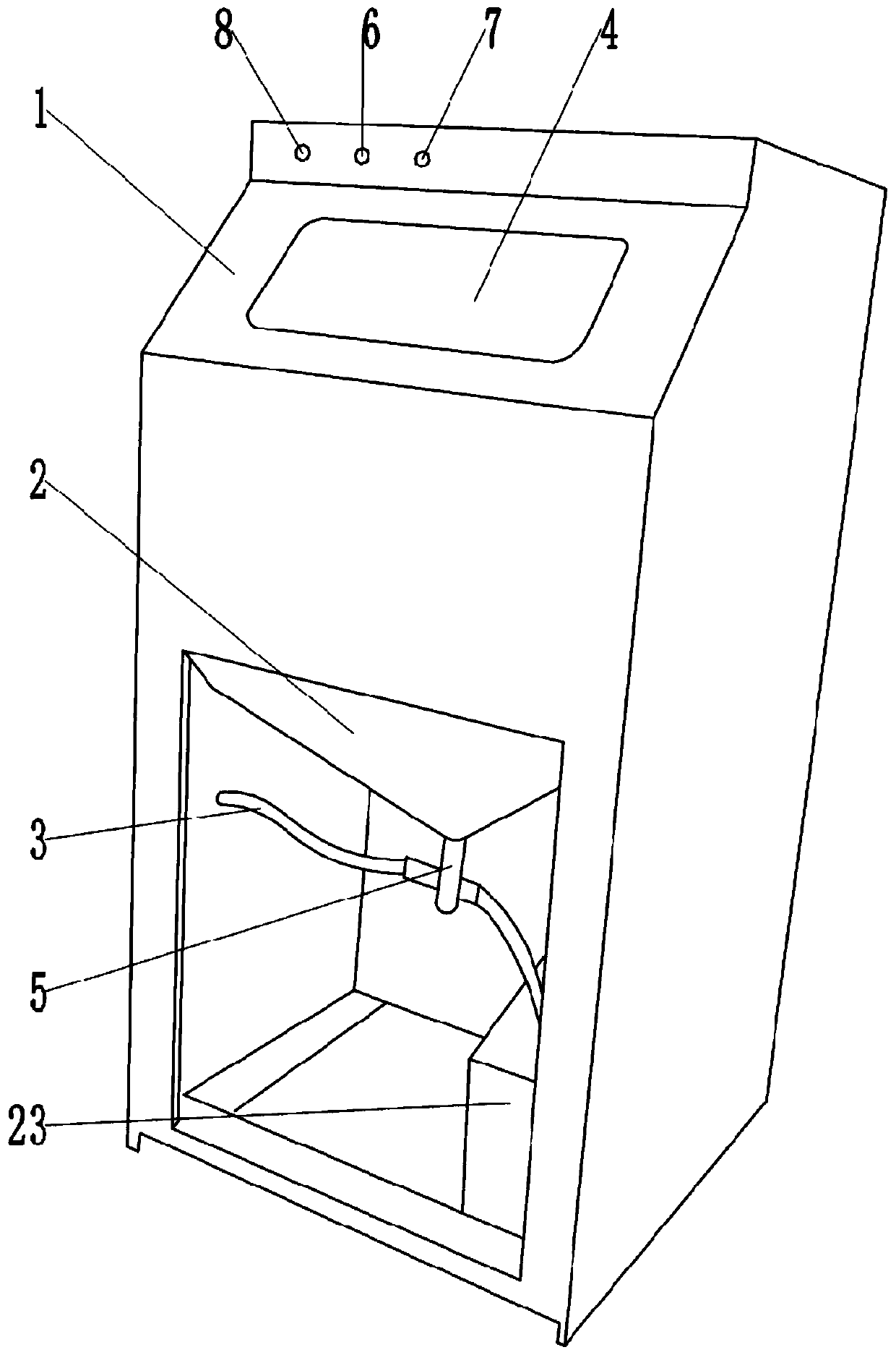
[0041] A sandblasting process applied to the shell of an environmental protection box mainly includes the following steps:

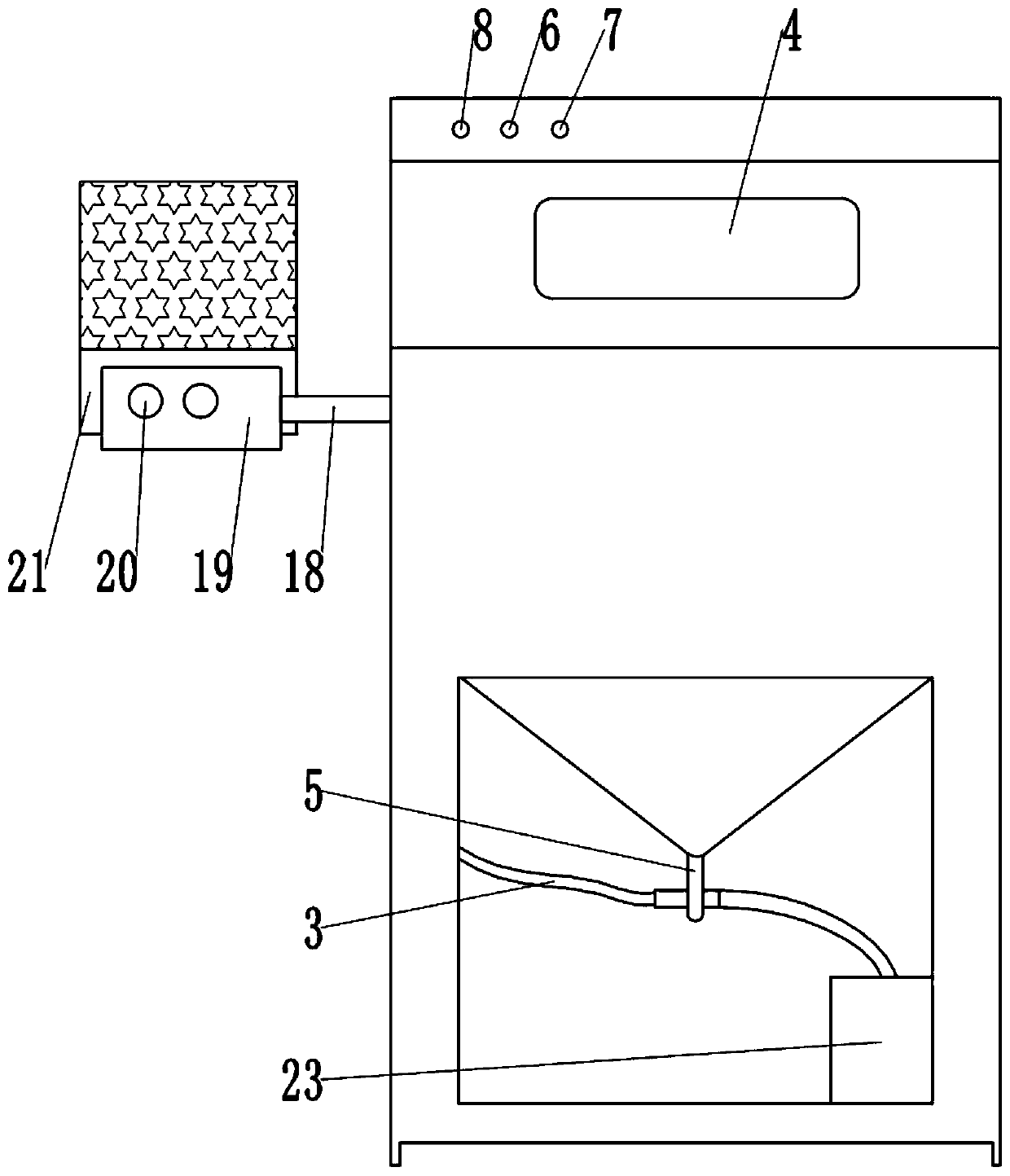
[0042] Step A, making the template 21: Hollow out the middle part of the template 21 by drilling or hollowing out, so that the hollowed out part forms the required pattern, so as to obtain the required template 21, such as figure 2 As shown, here take the form of a five-pointed star hollowed out on the template 21 as an example;

[0043] Step B, clean the base wall: clean the dust on the base wall, and repair the holes on the base wall; when there is a release agent on the base wall, use a wire brush to clean the release agent;

[0044] Step C, wetting the base wall surface: After the base wall surface is cleaned, spray water on the base wall surface to fully wet the base wall surface. The wetting depth is about 2-4mm. Here, 2.8mm is taken as an example for illustration;

[0045]Step D, sandblasting construction: because the prepared sandblasting mater...

Embodiment 2

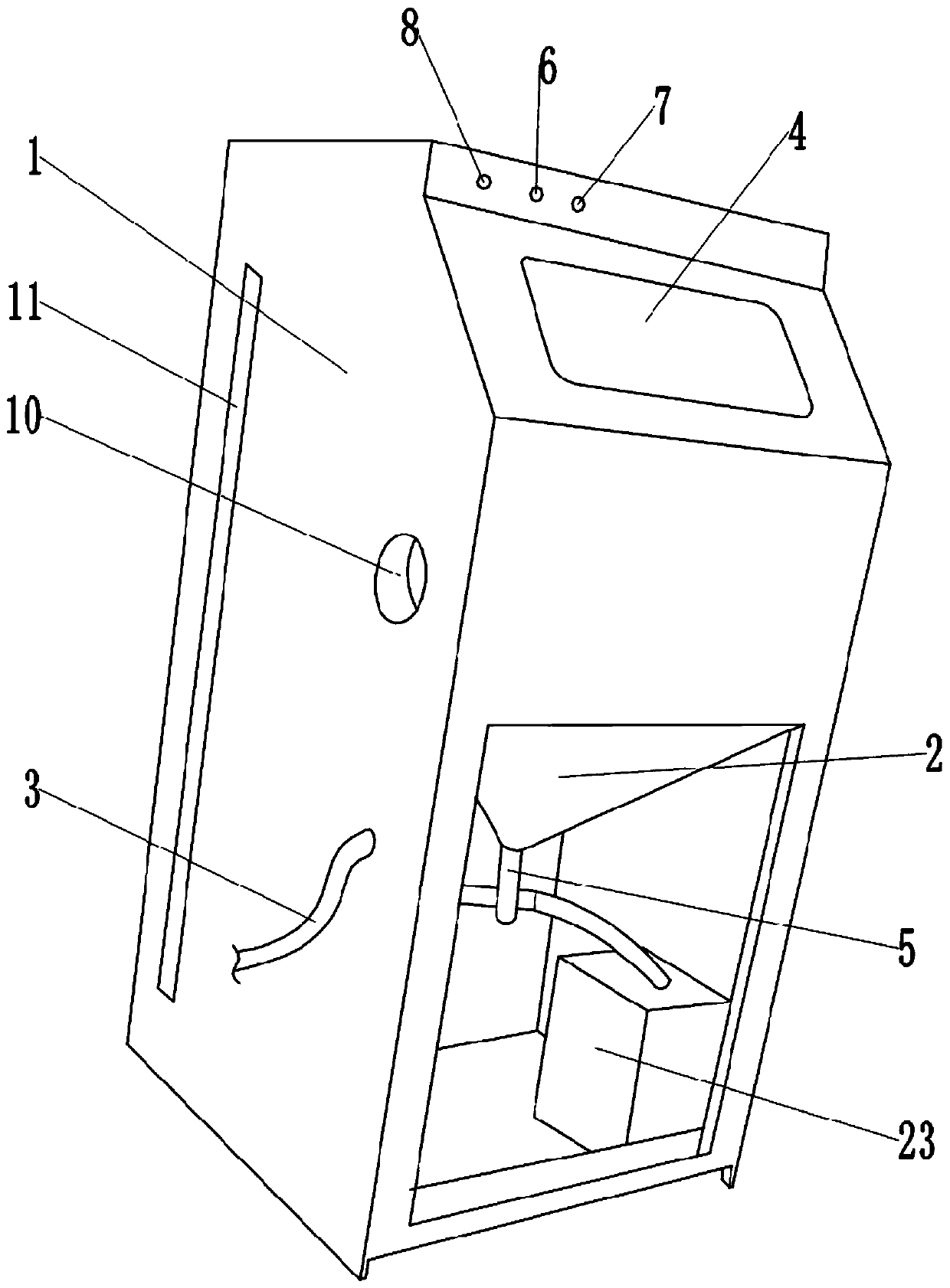
[0057] Such as Figure 5 As shown, the difference between this embodiment and Embodiment 1 is that the bottom of the stirring chamber is an inclined slope with a high left and a low right, and a feeding port 9 is provided on the right side of the bottom of the stirring chamber, and the feeding port 9 is located on the top of the sand storage bucket 2. side. The stirring chamber is connected with the stirring shaft 12 through the bearing rotation, and the stirring shaft 12 is inclined to the left and right, and the inclination angle of the stirring shaft 12 is the same as that of the bottom of the stirring chamber; the surrounding wall of the stirring shaft 12 is welded and fixed with multiple The stirring rod 17, the end of the stirring rod 17 away from the stirring shaft 12 can be in contact with the bottom of the stirring chamber, so that the stirring is more thorough. The insides of the stirring shaft 12 and the stirring rod 17 are hollow, and the stirring shaft 12 and the...

Embodiment 3

[0061] The difference between the present embodiment and the first embodiment is that there are multiple templates 21, and the same patterns are hollowed out on the multiple templates 21, and three templates 21 are used as examples for illustration. This scheme is mainly used in the situation where multiple identical patterns are formed by spraying on the base wall. When a single formwork 21 is worn out after repeated use or cannot reach the cleanliness required for construction, the operator can directly replace a formwork 21 to continue construction. .


PUM

PropertyMeasurementUnit
thicknessaaaaaaaaaa

Abstract

The invention relates to the technical field of environment-friendly box variable shell surface processing technology, in particular to a sand blasting process applied to an environment-friendly box variable shell. The process mainly comprises the process steps of cleaning dust on a base layer wall; and spraying water to the base layer wall to enable the base layer wall to be sufficiently wetted,carrying out sand blasting construction and water spraying maintaining and the like. Through the process, the technical problem that in the prior art, during manual broom-finish, the large concave andconvex difference easily exists can be solved, and the construction face is more flat.

Description

technical field [0001] The invention relates to the technical field of the surface treatment process of the shell of an environmental protection box, in particular to a sandblasting process applied to the shell of an environmental box. Background technique [0002] Sand blasting can change the monotonous appearance color, and can add brilliant colors to the shell of the environmental protection box, making it more artistic and ornamental. Sandblasting is a new decorative material, which is similar to but not identical to real stone paint. Sandblasting can form a relief pattern effect on the base wall. In the prior art, the method of manual roughening is used for processing, and the construction speed is very slow; moreover, the thickness of the artificial roughening is 3-10 mm, and the unevenness is relatively large, which easily leads to the technical problem of labor-intensive and material-intensive plastering and leveling processes. Contents of the invention [0003] T...

Claims


Application Information

Patent Timeline
Patent Type & Authority Applications(China)
IPC IPC(8): B24C1/04B24C7/00B24C11/00
CPCB24C1/04B24C7/0061B24C11/00
Inventor 彭信尧邹红潘尚义曹健崔振山刘兵袁野高歌周科廖勇
Owner CHONGQING WANGBIAN ELECTRIC GRP CORP
Why Eureka
Try Eureka