
Mechanical claw for machinery manufacturing

A technology of mechanical manufacturing and mechanical claws, which is applied in the field of mechanical manufacturing auxiliary devices, can solve problems such as high wear, increased user costs, and damage to surrounding objects, and achieve the effects of reduced production costs, good protection effects, and high safety

Active Publication Date: 2020-01-07
XIAN AERONAUTICAL POLYTECHNIC INST
View PDF10 Cites 2 Cited by
  • Summary
  • Abstract
  • Description
  • Claims
  • Application Information

AI Technical Summary

Problems solved by technology

[0003] However, the mechanical claws currently on the market for machinery manufacturing lack good protection when used. When the grasped object falls, it is difficult to stop it. This is because the falling object not only causes damage to surrounding objects, but also It poses a safety threat to the surrounding staff; at the same time, during the use of mechanical claws, there is usually a certain distance between the claws and the claws cannot be adjusted effectively. This is when grabbing smaller objects, it will be because Due to the distance between the claw and the claw, it cannot be grasped, so a new mechanical claw needs to be replaced, which will increase the user's cost and reduce the user's processing efficiency; at the same time, when the mechanical claw is damaged, it cannot It is convenient to disassemble and replace, especially at the tip of the claw, the degree of wear is high, and the grasping failure will occur after a long time

Method used


Image

  • Mechanical claw for machinery manufacturing
  • Mechanical claw for machinery manufacturing
  • Mechanical claw for machinery manufacturing

Examples


Embodiment 1

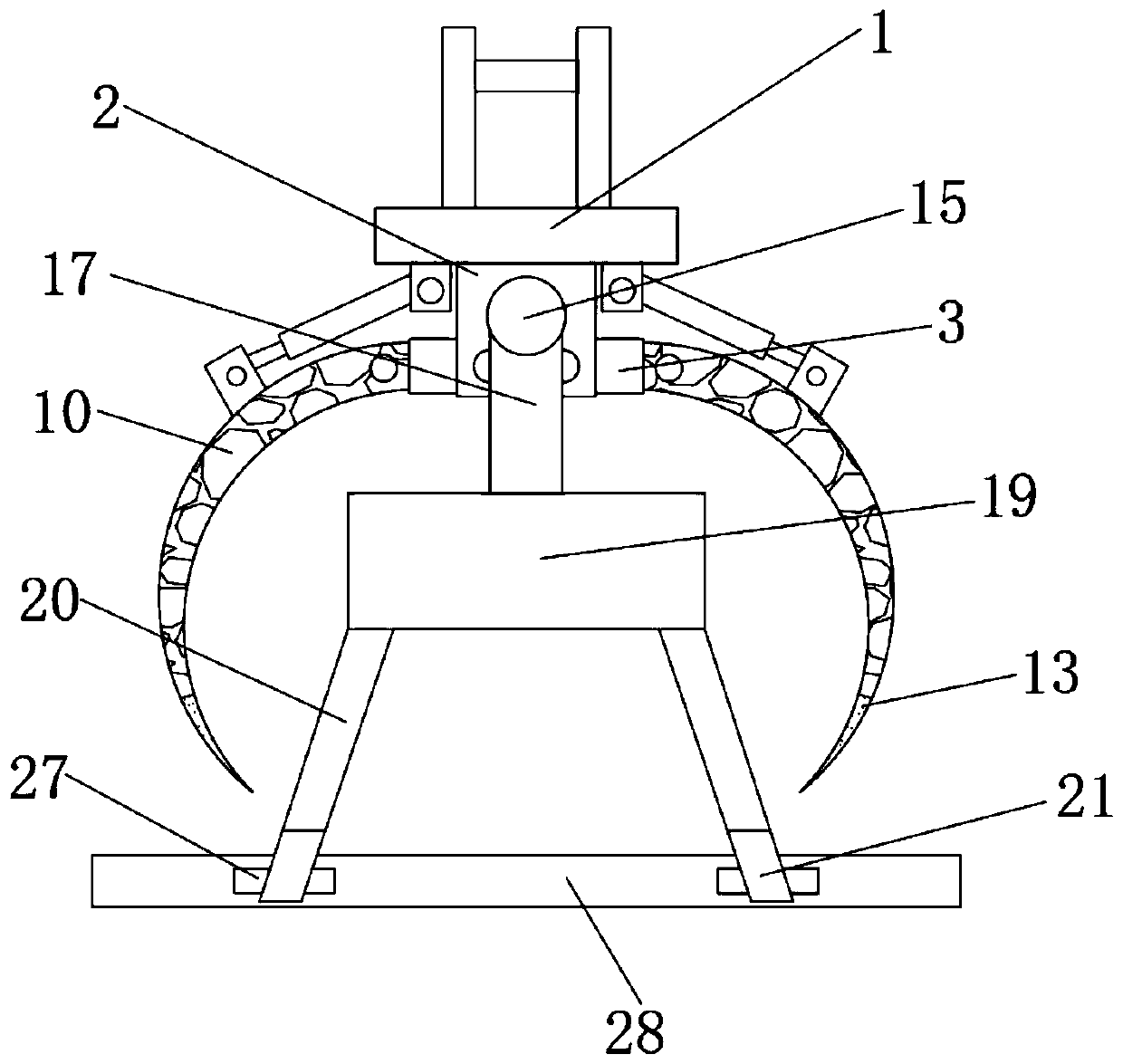
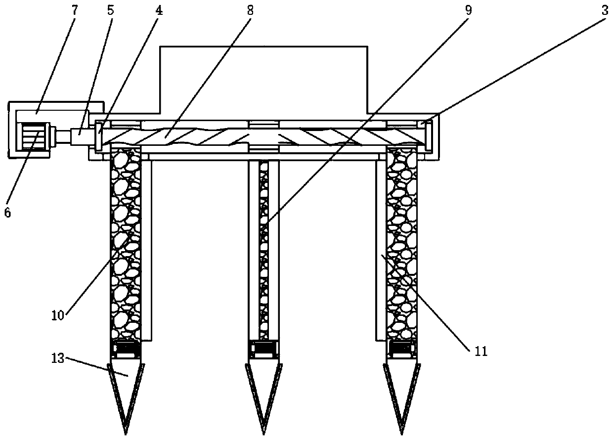
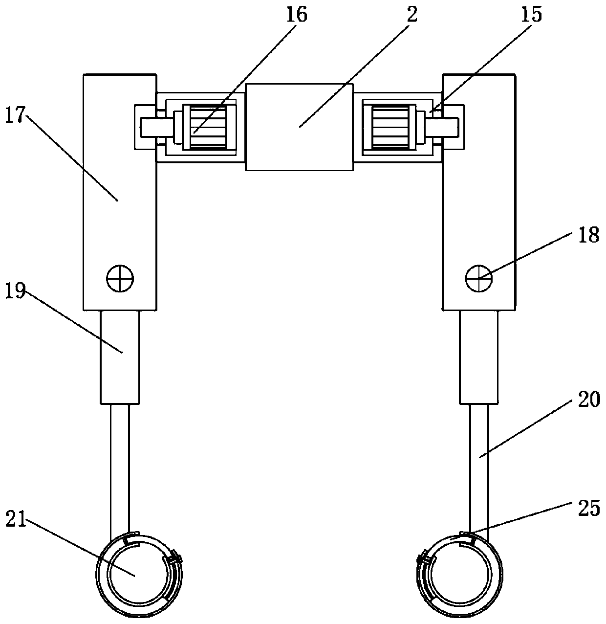
[0030] Depend on Figure 1-6 Provided, the present invention includes an assembly block 1, the bottom of the assembly block 1 is fixed with a retaining block 2, the side of the retaining block 2 is equipped with a positioning block 3, and the side of the cavity of the positioning block 3 is equipped with a bearing 4, through which the bearing 4 setting, so that the rotation of the adjustment rod 8 is more stable, the side of the bearing 4 is equipped with a transmission rod 5, through the setting of the transmission rod 5, the adjustment motor 6 can perform stable power transmission, and the transmission rod 5 extends to one end outside the positioning block 3 An adjusting motor 6 is installed, and the side of the adjusting motor 6 is equipped with a placement frame 7, and the other side of the bearing 4 is installed with an adjusting rod 8, and the middle part of the adjusting rod 8 is installed with a central claw 9, and one end of the adjusting rod 8 is threadedly connected ...

Embodiment 2

[0032] On the basis of Embodiment 1, the left and right sides of the surface of the retaining block 2 are matched with the sides of the positioning block 3, and the front and rear sides of the surface of the retaining block 2 are matched with the sides of the protective box 15, through the setting of the retaining block 2 , so that both the positioning block 3 and the protective box 15 are effectively installed, thereby using the positioning block 3 and the protective box 15 to realize different functions.

Embodiment 3

[0034] On the basis of Embodiment 1, parallel grooves are provided on the side of the branch claw 10, and the parallel groove on the branch claw 10 is on the same horizontal line as the top of the first screw 12. Through the setting of the branch claw 10, it can be used The parallel groove prevents the first screw 12 from protruding from the surface of the branch claw 10 , which reduces the appearance of the branch claw 10 .


PUM


Abstract

The invention discloses a mechanical claw for machinery manufacturing. The mechanical claw comprises an assembly block, and a retaining block is fixedly arranged at the bottom of the assembly block. Apositioning block is arranged on the side face of the retaining block, and a bearing is arranged on the side face of the inner chamber of the positioning block. A transmission rod is arranged on theside face of the bearing, and a regulating motor is arranged at the end, extending to the outer part of the positioning block, of the transmission rod; a placing rack is arranged on the side face of the regulating motor; a regulating rod is arranged on the other side of the bearing, and a central claw is arranged at the middle part of the regulating rod; one end of the regulating rod is in threaded connection with a branch claw, and a plug board block is fixedly arranged on the side face, positioned outside the positioning block, of the branch claw; and the top of the branch claw is in threaded connection with the top of a claw tip block through a first screw. In the mechanical claw, the distance between claws can be adjusted.

Description

technical field [0001] The invention belongs to the technical field of mechanical manufacturing auxiliary devices, and in particular relates to a mechanical claw for mechanical manufacturing. Background technique [0002] Machinery manufacturing refers to the industrial sector engaged in the production of various power machinery, lifting and transportation machinery, chemical machinery, textile machinery, machine tools, tools, instruments, meters and other mechanical equipment. The machinery manufacturing industry provides technical equipment for the entire national economy. [0003] However, the mechanical claws currently on the market for machinery manufacturing lack good protection when used. When the grasped object falls, it is difficult to stop it. This is because the falling object not only causes damage to surrounding objects, but also It poses a safety threat to the surrounding staff; at the same time, during the use of mechanical claws, there is usually a certain di...

Claims


Application Information

Patent Timeline
IPC IPC(8): B25J15/00B25J15/10
CPCB25J15/00B25J15/10
Inventor 孙剑伟杨帆王博华
Owner XIAN AERONAUTICAL POLYTECHNIC INST
Learn More