Unmanned aerial vehicle charging system

A charging system and unmanned aerial vehicle technology, applied in the field of unmanned aerial vehicles, can solve the problems of expensive and laborious, large number of unmanned aerial vehicles, etc., to achieve the effect of improving efficiency, realizing unmanned management, and avoiding manual wiring.

Pending Publication Date: 2020-01-07
GUANGDONG UNIV OF TECH
View PDF0 Cites 7 Cited by
  • Summary
  • Abstract
  • Description
  • Claims
  • Application Information

AI Technical Summary

Problems solved by technology

Since the batteries carried by drones generally have a battery life of 30 minutes, drones often need to be charged. In addition, in large-scale events such as lighting shows, the number of drones is huge, and manual wiring and charging is a costly and laborious task.

Method used


Image

  • Unmanned aerial vehicle charging system
  • Unmanned aerial vehicle charging system
  • Unmanned aerial vehicle charging system

Examples


Embodiment 1

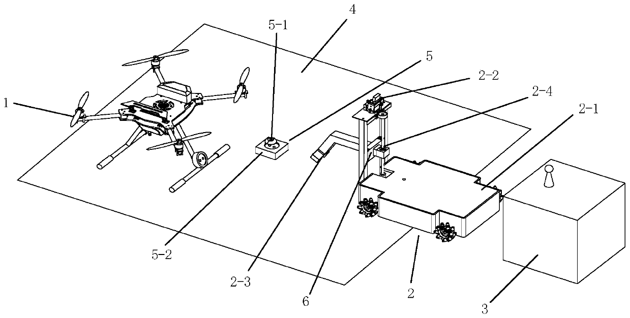
[0048] Such as Figure 1-2 As shown, a UAV charging system described in this embodiment includes a UAV 1, a mobile car 2, an auxiliary base station 3 and an apron 4;

[0049] UAV 1 is equipped with a charging interface;

[0050] The mobile trolley 2 includes a trolley main body 2-1, a camera module 2-2, a GPS module, a trolley communication module, a main controller, a manipulator 2-3, and a vertical lifting mechanism 2-4; wherein, the vertical lifting mechanism 2-4 is set up on The front end of the car main body 2-1 in the forward direction, the manipulator 2-3 slides and fixes with the vertical lift mechanism 2-4 through the fixing part 6, the camera module 2-2 is installed on the top of the vertical lift mechanism 2-4, the GPS module and the car communicate Both the module and the main controller are installed on the trolley main body 2-1, and the main controller is respectively connected with the camera module 2-2, the GPS module, and the trolley communication module;

...

Embodiment 2

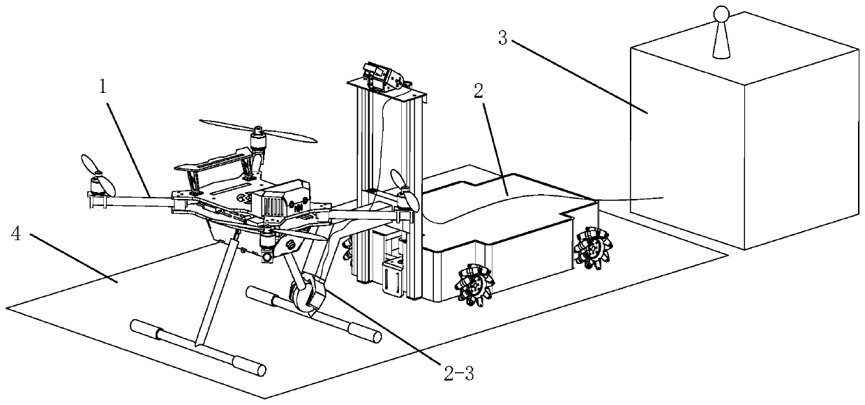
[0068] like image 3 As shown, compared with Embodiment 1 in Embodiment 2, there is no need to set charging module 5 on the ground surface of the apron 4;

[0069] The auxiliary base station 3 is also provided with a charging power supply to help the UAV 1 and the mobile car 2 to charge;

[0070] The charging interface carried by the UAV 1 is in the shape of a sphere with a charging interface marker, and the two parts opposite to the surface of the sphere are respectively provided with a positive pole and a negative pole connected to the battery of the UAV 1;

[0071] The manipulator 2-3 is a two-grip flexible manipulator, and the inner sides of the two fingers are respectively provided with a positive pole and a negative pole connected to the charging line directly pulled out from the charging power supply in the auxiliary base station 3;

[0072] When the manipulator 2-3 clamps the charging interface carried by the drone 1, the positive and negative poles of the two are con...

Embodiment 3

[0076] like Figure 4 As shown, compared with Embodiment 2 in Embodiment 3, the apron 4 is provided with a ceiling, and a power grid powered by the charging power supply of the auxiliary base station 3 is laid on the ceiling, and the trolley main body 2-1 is equipped with a power grid connected to the power grid. The vertical electric pole, the manipulator grasps the inner 2-3 positive and negative poles with two fingers to communicate with the vertical electric pole.

[0077] The difference between the working principle of the third embodiment and the working principle of the second embodiment is:

[0078] Change the UAV charging line originally connected to the manipulator 2-3 from the auxiliary base station 3 to the ground grid power supply mode, and there is a power grid on the ceiling of the apron 4, and the mobile car 2 passes through the vertical pole Power is taken from the ceiling, so that the charging lines of the drone will not cross, which is convenient for the ra...


PUM


Abstract

The invention discloses an unmanned aerial vehicle charging system. The system involves an unmanned aerial vehicle, a movable trolley, an auxiliary base station and a parking apron; the unmanned aerial vehicle is provided with a charging connector; the movable trolley comprises a trolley main body, a camera module, a GPS module, a trolley communication module, a main controller, a manipulator anda vertical lifting mechanism, wherein the vertical lifting mechanism is arranged at the front end of the advancing direction of the trolley main body in an erected mode, the manipulator is slidably fixed with the vertical lifting mechanism through a fixing part, the camera module is arranged at the top of the vertical lifting mechanism, the GPS module, the trolley communication module and the maincontroller are all arranged on the trolley main body, and the main controller is connected with the camera module, the GPS module and the trolley communication module correspondingly; and the auxiliary base station is provided with a base station communication module. The unmanned aerial vehicle charging system has the advantages of being simple and rapid in process, high in efficiency, high in stability, capable of saving manpower resources and the like.

Description

technical field [0001] The invention relates to the technical field of drones, in particular to a charging system for drones. Background technique [0002] The times are advancing, and the technology of drones continues to improve, making drones have entered people's daily life, and the number is increasing. For example, drones can be seen in areas such as danger rescue, lighting performances, and live events. figure. Since the batteries carried by drones generally have a battery life of 30 minutes, drones often need to be charged. In addition, in large-scale events such as light shows, there are a large number of drones, and manual wiring and charging is a costly and laborious task. Contents of the invention [0003] The purpose of the present invention is to overcome the deficiencies of the prior art and provide a charging system for unmanned aerial vehicles with simple and quick process, high efficiency, high stability and saving human resources. [0004] In order to ...

Claims


Application Information

Patent Timeline
Patent Type & Authority Applications(China)
IPC IPC(8): B60L53/30B60L53/16B60L53/60B64F1/00
CPCB60L53/16B60L53/30B60L53/60B60L2200/10B64F1/00Y02T10/70Y02T10/7072Y02T90/12Y02T90/14Y02T90/16
Inventor 叶树芬苏成悦
Owner GUANGDONG UNIV OF TECH
Why Eureka
Try Eureka