
Brake lamp sensor

A sensor and brake light technology, applied in optical signals, signaling devices, transportation and packaging, etc., can solve problems such as affecting driving safety, power failure, loss of two-way signals BLS and BTS, etc., to avoid complete loss. Effect

Inactive Publication Date: 2020-01-07
DONGFENG LIUZHOU MOTOR
View PDF8 Cites 0 Cited by
  • Summary
  • Abstract
  • Description
  • Claims
  • Application Information

AI Technical Summary

Problems solved by technology

[0005] The purpose of the present invention is to provide a brake light sensor, which can solve the problem in the prior art that one power supply fails and two signals BLS and BTS are lost, which affects driving safety.

Method used


Image

  • Brake lamp sensor

Examples


Embodiment Construction

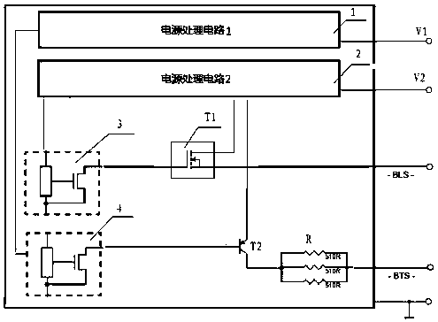
[0013] Below in conjunction with accompanying drawing and embodiment the present invention is described in further detail:

[0014] figure 1 The brake light sensor shown includes a power processing circuit, and there are two power processing circuits, one is the first power processing circuit 1, and the other is the second power processing circuit 2, the first power processing circuit 1 is the first Hall The element 3 provides working power, the second power processing circuit 2 provides working power for the second Hall element 4, the output terminal of the first Hall element 3 outputs a signal through the first switch tube T1, and the output of the second Hall element 4 The terminal outputs a signal through the second switch tube T2; the first switch tube T1 gets power from the first power processing circuit 1, and the second switch tube T2 gets power from the second power processing circuit 2. The output end of the second switch tube outputs a signal through the output res...


PUM


Abstract

The invention discloses a brake lamp sensor, and relates to the technical field of automobile manufacturing. The brake lamp sensor comprises two power source processing circuits, one is a first powersource processing circuit and the other is a second power source processing circuit, the first power source processing circuit provides a working power source for a first Hall element, the second power source processing circuit provides a working power source for a second Hall element, the output end of the first Hall element outputs a signal through a first switch tube, and the output end of thesecond Hall element outputs a signal through a second switch tube; and the first switch tube acquires a power source from the first power source processing circuit, and the second switch tube acquiresa power source from the second power source processing circuit. According to the brake lamp sensor, the problem that in the prior art, one path of power is powered down, then the two paths of signalsof BLS and BTS are lost, and the driving safety is influenced can be solved.

Description

technical field [0001] The invention relates to the technical field of automobile manufacturing, in particular to a brake light sensor with two independent redundant power supplies. Background technique [0002] The brake light sensor consists of a Hall-effect based sensor driven by a permanent magnet mounted on the brake master cylinder, which moves synchronously with the brake master cylinder piston. The working mechanism of the sensor is based on changing the distance between the permanent magnet and the Hall element in the sensor to change the Hall voltage. When the brakes are applied, the piston movement causes the magnet to move past the brake light sensor, achieving a magnetic flux where signal switching can occur. When the brake pedal is released, the permanent magnet returns to its initial position. [0003] The brake light sensor is a sensor that converts displacement changes into high and low level electrical signal outputs. Two Hall elements are designed on th...

Claims


Application Information

Patent Timeline
IPC IPC(8): B60Q1/44
CPCB60Q1/44
Inventor 唐竞林长波陈江深黄东杰张德军龙文钟永普陈锐李伟伟陈裴杨继业梁宝梯覃健覃权中罗斯宇蓝伟黄富达
Owner DONGFENG LIUZHOU MOTOR
Features
  • Generate Ideas
  • Intellectual Property
  • Life Sciences
  • Materials
  • Tech Scout
  • Unparalleled Data Quality
  • Higher Quality Content
  • 60% Fewer Hallucinations
Learn More