
Redundancy in UAV engine timing position systems

Active Publication Date: 2017-05-18
ORBITAL ENGINE CO PTY LTD
View PDF18 Cites 8 Cited by
  • Summary
  • Abstract
  • Description
  • Claims
  • Application Information

AI Technical Summary

Benefits of technology

The present invention provides a light-weight redundant timing system for UAV engines. This system has a single timing position sensor instead of multiple sensors, which helps to reduce weight and space. The system also includes a secondary timing position determining means that can safely return the UAV to base or at least land safely if there is a failure in the main timing position sensor. The secondary timing position determining means can also synchronize engine timing in case of failure or loss of the main sensor. The synchronization signal can be obtained from a primary crankshaft position sensor, and the signal no longer needs to be used after the engine is running. Overall, this invention helps to increase engine operating time through reduced fuel consumption, increase airspeed, and improve safety for UAV applications.

Problems solved by technology

Whilst it may be desirable to omit components and control system parts to provide weight benefits in certain engines, minimising components in engine systems, particularly where this may impact on any redundancy capability, can however lead to an increased risk of engine failure, and ultimately potentially complete loss of the UAV.
UAVs need to be reliable because the consequences of mechanical or electrical failure (such as engine mechanical failure or engine sub-system failure e.g. the engine timing system) can be very severe.
If a UAV in some way fails whilst flying, this can result in the ultimate demise and destruction of the UAV when it falls back down to the ground.
Also, such failure can happen when the UAV is a long way from its base and potentially over dangerous or difficult terrain, making safe recovery risky or impossible.
There is also the associated risk of losing very expensive surveillance or other equipment carried by the UAV.
However, this tends to lead directly to increased UAV weight and also additional unit and replacement costs.
Furthermore in terms of reliability, having only one system on-board does not allow for any failure at all of the engine timing system.
This may also not satisfy certain regulatory requirements for such aerial vehicles when used in specific applications.
However, merely duplicating the primary engine timing system can significantly impact desired weight and space constraints of the UAV which can in turn reduce performance and range of the UAV.
Such duplication can also result in an increase of the overall cost of UAV.
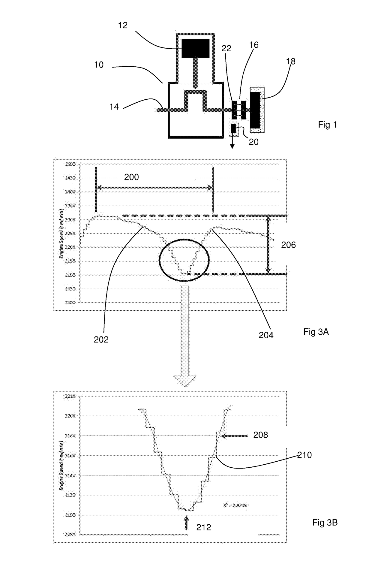
For example, for engines utilising a rotary encoder having a toothed / notched timing indicator wheel on an end of the crankshaft and a fixed sensor (such as a magnetic or optical sensor) to detect when a timing indicator on the wheel passes the sensor, adding a second such timing indicator wheel and sensor arrangement (or at the very least a second sensor detecting the timing indicator on the first wheel and having electronics to compensate for the different rotational position of the timing indicator) would add significant complexity and weight to the UAV.
Also, duplicating the primary engine timing system components invariably adds to the cost of the UAV engine systems, not least because the primary engine timing system components needing to be robust are therefore relatively expensive.
Whilst it would be beneficial to have full engine timing system redundancy with two matching (duplicated) engine timing systems for UAV engines, the added weight and space of the complete second system would be too detrimental to performance and the effect on cost would also be an issue.
That is, an engine timing system along these lines which includes full duplicated standard engine timing systems, one serving as a primary system, and one for backup / redundancy purposes, would make for an uncompetitive overall engine package.
As discussed above, the mere duplication of parts to provide such redundancy capability in such UAV aircraft systems is in conflict with the requirement to keep weight to a minimum.
However, these typically require either duplication of components to provide redundancy, or have additional components that are used to emulate a timing signal or help derive a timing signal.
Such systems do not provide for partial redundancy of an engine timing system which fulfils the need for operational redundancy without incurring a significant weight (and cost) penalty incurred by direct duplication of timing system components or adding other components that are used to emulate or replace components in order to generate a replacement timing signal, and thus add significantly to weight and cost.
Thus, U.S. 2007 / 0256482 adds a second crankshaft position sensor and associated connections and processing to generate the emulated second crankshaft position signal stream, which adds weight and cost to the engine / vehicle.
This clearly adds cost and weight to the engine.

Method used


Image

  • Redundancy in UAV engine timing position systems
  • Redundancy in UAV engine timing position systems
  • Redundancy in UAV engine timing position systems

Examples


Embodiment Construction

[0075]The present invention provides for redundancy in engine timing position sensing to maintain a UAV operational (at least in a ‘limp home’ mode of operation) in the event of failure of a primary engine timing position sub-system (such as failure of a crankshaft rotary encoder / sensor).

[0076]One or more forms of the present invention provides for such redundancy without requiring duplication of the primary crankshaft timing position sensing components, and thereby avoids adding weight, cost and component complexity.

[0077]Avoiding additional weight within a UAV is very important as it means that range and / or duration (such as loitering time) can be increased, providing a substantial advantage for the UAV operator. Any advantage in keeping overall weight down means that the UAV uses less fuel to take-off and / or uses less fuel when cruising or loitering (which lead to greater duration in time and / or distance covered compared with a heavier vehicle). Alternatively, for a lower vehicle...


PUM


Abstract

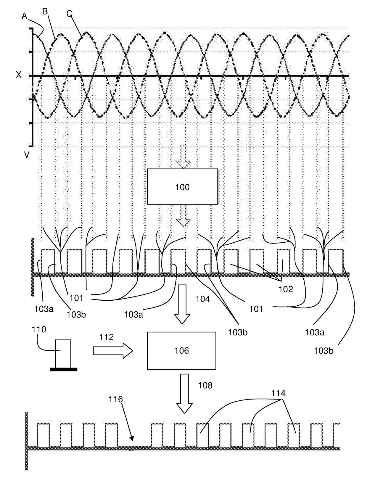
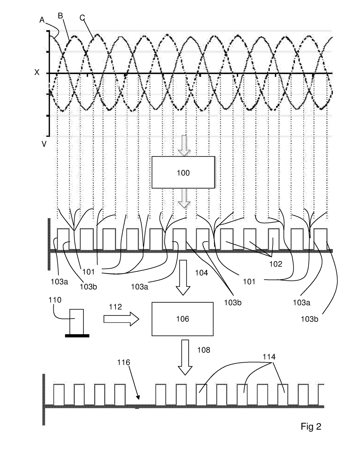
Redundancy in engine timing position sensing maintains a UAV operational in the event of failure of a primary engine timing position sub-system. The redundancy avoids duplication of the primary crankshaft timing position sensing components, and avoids adding weight, cost and component complexity. Conditioned (square) waveform(s) (102) is / are created from respective sinusoidal waveform(s). Each consecutive leading edge (103a) and trailing edge (103b) of the pulses of the square waveform (102) is derived from the crossing of the zero voltage value by consecutive sinusoidal waveforms A,B,C (e.g. Voltage (V) vs Time (t) or angular degrees). The square pulse waveform (102) is output (104) to a microcontroller (106) to create and output a pseudo crankshaft timing position signal (108) to be used by an ECU to determine ignition and fuel injection events in the event that the primary timing signal from the crankshaft position sensor (CPS) has failed. The signal (108) output to the ECU can have a missing pulse (116) (i.e. indicative of a TDC position of the engine crankshaft) as well as multiple square pulses (114) corresponding to the pulses of the initial square pulse waveform (102). The waveform signal (108) is therefore derived from the alternator waveform signal(s) and provides a pseudo crankshaft timing position signal in the event of failure of the primary or initial CPS signal.

Description

FIELD OF THE INVENTION[0001]The present invention relates to control of engines used in unmanned aerial vehicles.[0002]The present invention is particularly applicable to redundancy in engine timing position determination for operation of UAV engines.BACKGROUND TO THE INVENTION[0003]Unmanned aerial vehicles (UAVs) require range and durability in the air. To help achieve this, engines and their control systems for such UAVs need to be relatively light in weight and yet provide high performance.[0004]One way to achieve lightness in weight is to omit as many non-essential components and control system parts as possible and / or to make such components lightweight. However, to survive in the extreme ambient conditions that UAVs are exposed to, the engine and its control systems also need to be robust and reliable.[0005]Engine timing position sensing is an essential part of engine control. Without sensing of the rotational position of the crankshaft, camshaft or related rotational componen...

Claims


Application Information

Patent Timeline
IPC IPC(8): F02D41/00B64C39/02H02K11/21F02D41/22
CPCF02D41/009F02D41/222B64C39/024B64C2201/044F02D2400/08F02D2200/101H02K11/21Y02T10/40B64U10/10B64U50/11B64U10/00
Inventor UTLEY, TYRON DEANBUTERS, NICOLASS HARRYNARAYAN, JAYESH
Owner ORBITAL ENGINE CO PTY LTD
Features
  • Generate Ideas
  • Intellectual Property
  • Life Sciences
  • Materials
  • Tech Scout
  • Unparalleled Data Quality
  • Higher Quality Content
  • 60% Fewer Hallucinations
Learn More