Ceramic substrate feeding mechanism

A ceramic substrate and silo technology, applied in the field of ceramic substrate feeding mechanism, can solve the problems of low operation efficiency and low degree of automation, and achieve the effect of low cost, high degree of automation, stable and reliable operation

Pending Publication Date: 2020-01-07
苏州鸣动智能设备有限公司
View PDF0 Cites 0 Cited by
  • Summary
  • Abstract
  • Description
  • Claims
  • Application Information

AI Technical Summary

Problems solved by technology

The general loading mechanism can only work on one jig at the same time. After the loading is completed, the empty jig needs to be manually taken out and put back into the jig. The degree of automation is low and the operation efficiency is low.

Method used


Image

  • Ceramic substrate feeding mechanism
  • Ceramic substrate feeding mechanism
  • Ceramic substrate feeding mechanism

Examples


Embodiment

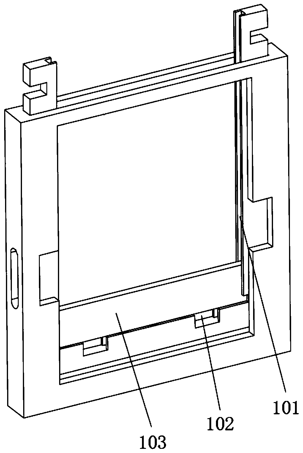
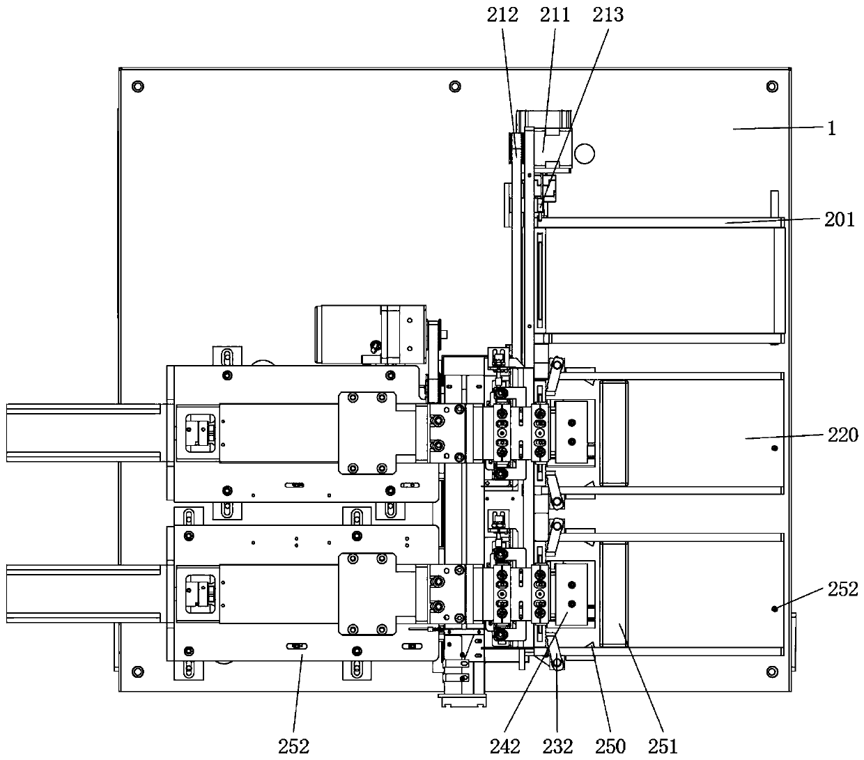
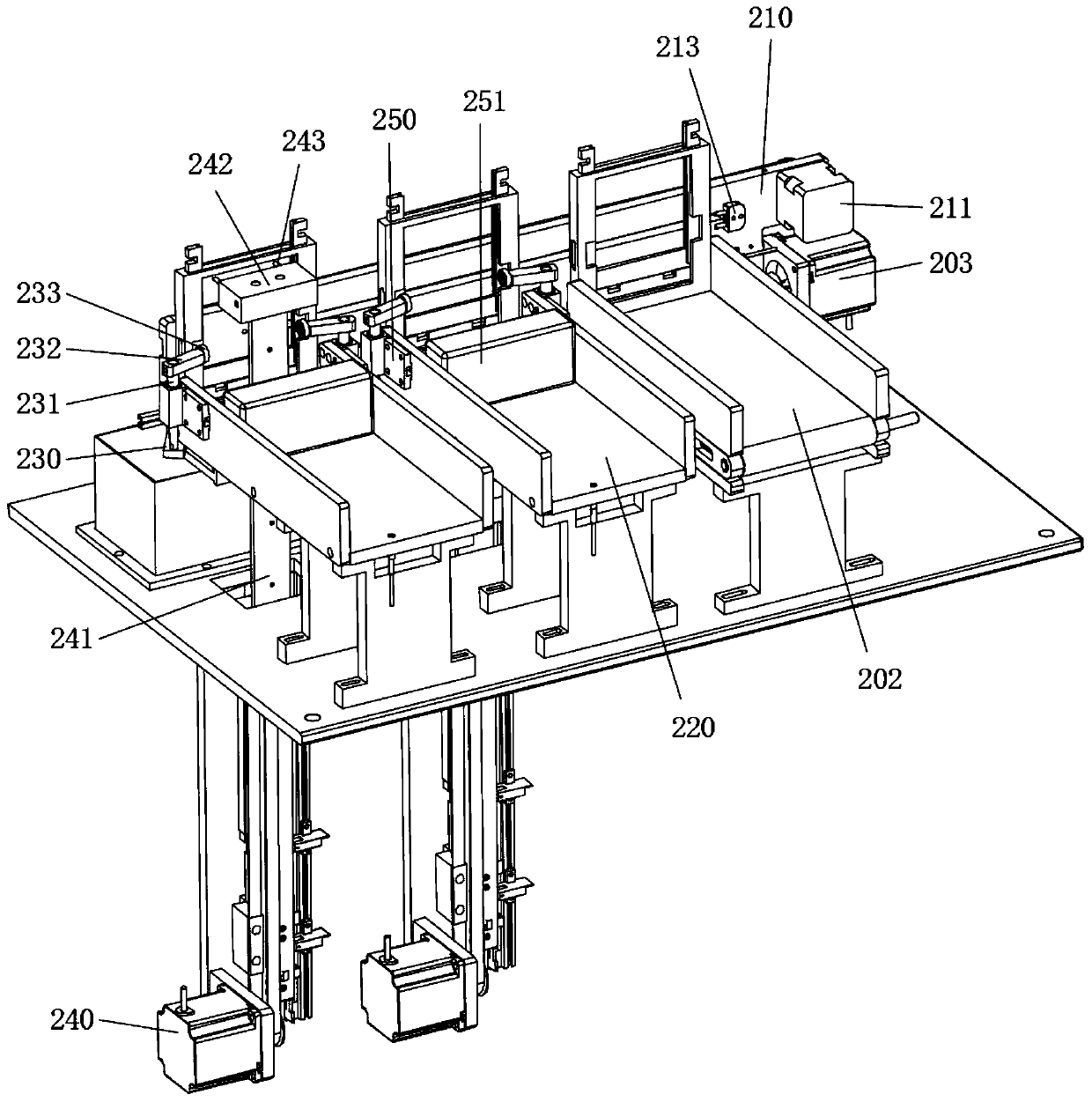
[0028] refer to Figure 1 ~ Figure 4 As shown, the present invention discloses a ceramic substrate feeding mechanism, which includes a base 1, an upper jig unit, a jig transfer unit, an upper bin 220, a jig positioning unit, an ejection unit and a lower jig unit.

[0029] Upper fixture unit:

[0030] The above-mentioned upper jig unit includes a jig bin 201 , a jig conveying belt 202 and a jig conveying driving source 203 .

[0031] The above-mentioned jig bin 201 is mounted on the base 1 . Both sides of the jig chamber 201 are provided with a baffle plate 1 . The spacing between the two baffle plates is consistent with the width of the jig. The distance between the end of one baffle plate 1 and the transfer plate 210 is smaller than the thickness of the jig, and the distance between the end of the other baffle plate 1 and the transfer plate 210 is equal to the thickness of the jig.

[0032] The jig conveyor belt 202 is arranged at the bottom of the jig bin 201 . The jig ...


PUM


Abstract

The invention discloses a ceramic substrate feeding mechanism comprising a base, an upper jig unit, a jig transfer unit, feeding bins, an ejection unit and a lower jig unit. The upper jig unit comprises a jig bin, a jig conveyor belt ad a jig conveying drive source. The jig transfer unit comprises a transfer plate. A jig transfer drive source and a horizontal jig transfer belt are arranged on thetransfer plate. A jig transfer head is arranged on the jig transfer belt. The feeding bins are arranged on the base. The ejection unit comprises lifting drive sources, a telescopic drive source and atelescopic plug. The telescopic plug is arranged at the free end of the telescopic drive source. The lower jig unit comprises non-return assemblies, stop pieces, a retreating drive source and a retreating fork. Each non-return assembly is arranged on the corresponding feeding bin. Each stop piece is arranged in the corresponding feeding bin in a sliding manner. The retreating fork is arranged at the free end of the retreating drive source. The sintering machine material distribution control system is high in automation degree, stable and reliable in operation and simple in structure, saves manpower and material resources and is low in cost.

Description

technical field [0001] The invention relates to a feeding mechanism, in particular to a ceramic substrate feeding mechanism. Background technique [0002] During the production process of the ceramic substrate, a preliminary cutting is carried out on the ceramic substrate, and then the ceramic substrate is split into strips, and finally the strip-shaped ceramic substrate is disassembled into granular ceramic substrates. In the process of ceramic base grains from strips to grains, it is usually necessary to place them on a jig (see figure 1 ) in the ceramic base strip. There is usually a stacking groove in the jig, and a lifting block is slidably arranged at the bottom of the stacking groove, and a lifting opening is opened on the jig at the bottom of the lifting block. The ceramic base strips stacked in the stacking groove can be separated from the stacking groove upwards under the drive of the lifting block. The general loading mechanism can only work on one jig at the s...

Claims


Application Information

Patent Timeline
Patent Type & Authority Applications(China)
IPC IPC(8): B65G59/04B65G47/06B65G47/82B65G1/04B65G49/08
CPCB65G1/04B65G47/06B65G47/82B65G49/08B65G49/085B65G59/045
Inventor 胡凤鸣黄向阳王海红梁海伟
Owner 苏州鸣动智能设备有限公司
Why Eureka
Try Eureka