A machining coolant filter device

A filtration device and machining technology, applied in filtration separation, filtration treatment, fixed filter element filter, etc., can solve the problems of low filtration efficiency, clogging of the filter screen, damage to the blades of the lift pump, etc. Inexpensive, efficiency-enhancing effects

Active Publication Date: 2020-08-25
张喜成
View PDF3 Cites 0 Cited by
  • Summary
  • Abstract
  • Description
  • Claims
  • Application Information

AI Technical Summary

Problems solved by technology

[0004] Coolant needs to be recycled. It mainly pumps the coolant through a lift pump and then outputs it. The coolant contains more particles. Therefore, if the coolant is not properly filtered, the lift pump will be damaged. Damaged blades, or blockage of coolant nozzles
[0005] The traditional filtering method is to use a filter for passive filtering, which has a low filtration efficiency, and the filter is often blocked, resulting in a temporary insufficient supply of coolant

Method used


Image

  • A machining coolant filter device
  • A machining coolant filter device
  • A machining coolant filter device

Examples


Embodiment 1

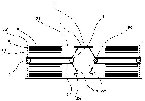
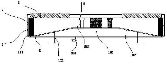
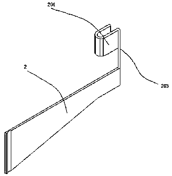
[0040] refer to figure 1 , figure 2 , image 3 with Figure 4 The shown machining coolant filtering device includes a separation tank 1, a platform surface 101 for diversion is provided at the bottom of the separation tank 1, and flow guides are formed on both sides of the platform surface 101. surface 102, the end of the diversion surface 102 away from the platform surface 101 is inclined downward, and four partitions 2 are symmetrically arranged in the front and rear inside the separation tank 1, and the partitions 2 are formed between the front and rear partitions. A channel 201 for separating non-magnetic chips, the side of the partition 2 away from the channel 201 forms a chamber 202 for separating magnetic chips, and the side of the partition 2 away from the center of the separation tank 1 One end is welded to the wall of the separation tank 1 to form a seal, and the end of the partition plate 2 away from the wall of the separation tank 1 is bent outward to form a di...

Embodiment 2

[0042] refer to Figure 5 with Image 6 As shown, the bottom of the adsorption plate 6 is movably installed between the separation tank 1, and a bead 131 is installed on the top of the separation tank 1, and the bead 131 is screwed to the separation tank 1, and the bottom of the bead 131 is A plurality of slots 141 for positioning the adsorption plate 6 are provided; more particles will be attached to the adsorption plate, if the adsorption plate is designed as a fixed structure, the particles on the adsorption plate need to be scraped when cleaning. However, the scraped particles will be re-adsorbed to the adsorption plate, resulting in ineffective cleaning. Therefore, we have designed the adsorption plate to be movable and fixed by pressing strips. When the adsorption plate needs to be cleaned, it can be removed. Pressing strips to remove the restriction on the adsorption plate. At this time, the adsorption plate can be taken out and cleaned, and then put back after cleanin...

Embodiment 3

[0044] refer to Figure 7 , Figure 8 , Figure 9 with Figure 10 As shown, a separation cylinder 9 is screwed at the inner bottom position of the intermediate cavity 205, and the filter hole diameter of the separation cylinder 9 is 0.5 mm ~ 1.2 mm, between the front and rear two closed plates 4 A cage 10 is welded, and the central position of the cage 10 is processed to form an annular body 11 assembled on the periphery of the separation cylinder 9, and a first cage 12 is welded between the two closing rods 502, The middle position of the first cage 12 is processed to form a first annular body 13 assembled on the periphery of the separation cylinder 9; the above-mentioned structure is mainly for the convenience of operation. First, the design of the separation cylinder is for cooling liquid Coarse filtration, the coarsely filtered particles can be quickly cleaned, reducing the filtration pressure on the adsorption plate and filter cartridge, the design of the cage can oper...


PUM

PropertyMeasurementUnit
pore sizeaaaaaaaaaa

Abstract

The invention discloses a machining cooling liquid filtering device including a separation tank; a platform surface for shunting is arranged at the tank bottom of the separation tank; guide faces areprocessed on two sides of the platform surface. The end, away from the platform surface, of the guide faces inclines downwards; four partition plates are symmetrically arranged in front of and behindthe interior of the separation tank; a channel used for separating non-magnetic chips is formed between a front partition plate and a rear partition plate. A cavity for separating magnetic chips is formed in one side, far away from a channel, of each partition plate; one end, far away from the center of the separation tank, of each partition plate is welded with the tank wall of the separation tank to form a seal; one end, far away from the tank wall of the separation tank, of each partition plate is bent outwards to form a guide face, and one end, far away from the corresponding partition plate, of each guide face is bent to form a U-shaped fixing part. According to the product, a double-selectable filtering mode can be adopted to reasonably filter a cooling liquid, and rapid filtering ofthe cooling liquid is achieved.

Description

technical field [0001] The invention relates to a machining cooling liquid filtering device. Background technique [0002] Lathe processing is a part of mechanical processing. There are mainly two processing forms: one is to fix the turning tool to process the unformed workpiece during rotation, and the other is to fix the workpiece and rotate the workpiece at high speed. The horizontal and vertical movement of the tool holder) for precision machining. Drills, reamers, reamers, taps, dies and knurling tools can also be used for corresponding processing on the lathe. Lathes are mainly used to process shafts, disks, sleeves and other workpieces with rotating surfaces, and are the most widely used type of machine tool processing in machinery manufacturing and repair factories. [0003] During lathe processing, it is necessary to cool the processed workpiece with coolant. The main function of the coolant is to reduce the temperature of the cutter head, prevent the workpiece ma...

Claims


Application Information

Patent Timeline
Patent Type & Authority Patents(China)
IPC IPC(8): C02F1/28C02F1/48C02F1/00B01D29/11B01D29/54B01D29/96
CPCB01D29/11B01D29/54B01D29/96C02F1/001C02F1/28C02F1/48C02F2303/16
Inventor 张喜成
Owner 张喜成
Why Eureka
Try Eureka