
Imaging-based micro-distance measuring device, method and equipment

A measurement device and measurement method technology, applied in the direction of measurement device, optical device, instrument, etc., can solve the problems of inability to meet measurement requirements, complex operations and algorithms, measurement object damage, etc., to improve recognition ability and high test accuracy. , the effect of accurate measurement results

Inactive Publication Date: 2020-01-07
SHANDONG NORMAL UNIV
View PDF9 Cites 0 Cited by
  • Summary
  • Abstract
  • Description
  • Claims
  • Application Information

AI Technical Summary

Problems solved by technology

[0004] The inventors of the present disclosure found that when the measurement size is further reduced and the accuracy requirements are further improved, the measurement requirements cannot be met by using traditional devices, and the measurement objects are easy to be damaged due to artificial force and other reasons during measurement, and there is a large artificial error
The new macro-distance measurement devices mostly use optical principles, such as optical projectors, laser interferometers, optical microscopes, etc., and their measurement accuracy is higher, reaching the order of microns and nanometers, but these measurement devices require higher costs, or more for complex operations and algorithms

Method used


Image

  • Imaging-based micro-distance measuring device, method and equipment
  • Imaging-based micro-distance measuring device, method and equipment
  • Imaging-based micro-distance measuring device, method and equipment

Examples


Embodiment 1

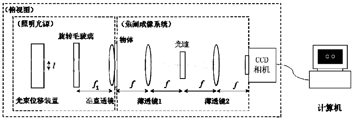
[0046] Such as figure 1 As shown, Embodiment 1 of the present disclosure provides an imaging-based macro-distance measurement device, which mainly includes an illumination source, an object to be measured, an imaging system, and a CCD camera connected to a computer.

[0047] Among them: the illumination source is constructed by two fiber laser sources, a beam displacement device (which can precisely control the distance between two fibers), rotating frosted glass and a collimating lens;

[0048] The imaging system is a 4f imaging system composed of two identical thin lenses, and a pupil is placed on its spectrum plane. This imaging system is also called a telecentric imaging system;

[0049] In addition, the CCD camera records the measured light intensity values ​​in grayscale values, and the grayscale values ​​can be read and processed by the commercial software matlab. In order to make the analysis simple and clear, we only consider the horizontal direction.

[0050] (1) L...

Embodiment 2

[0095] Embodiment 2 of the present disclosure provides a macro-distance measurement device, including the imaging-based macro-distance measurement device described in Embodiment 1 of the present disclosure.


PUM

PropertyMeasurementUnit
diameteraaaaaaaaaa

Abstract

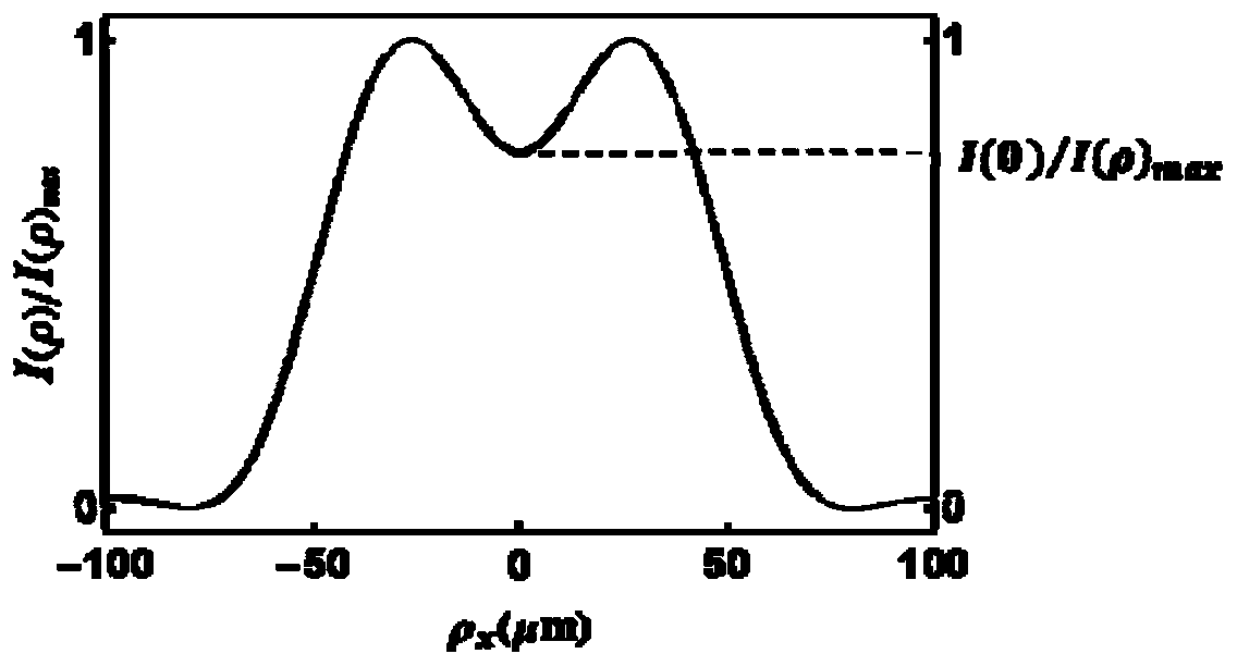
The disclosure provides an imaging-based micro-distance measuring device, method and equipment. The imaging-based micro-distance measuring device comprises an illumination light source, a to-be-measured object, an imaging system and a CCD camera connected with a processor. The illumination light source sequentially consists of two optical fiber laser sources, a light beam displacement device, rotary frosted glass and a collimating lens. A light beam passes through the rotary frosted glass and then is emitted to a to-be-measured object through the collimating lens. The imaging system is a 4f imaging system with a pupil arranged at a frequency spectrum surface. The CCD camera is arranged at the imaging surface of the imaging system and is used for detecting a maximum light intensity value and a central light intensity value of the imaging surface position. The processor is used for acquiring a distance between two end points of the to-be-detected object according to the wavelength of a light beam at a minimum ratio of the central light intensity value to the maximum light intensity value, a distance between two light beams on the rotary frosted glass, and the focal length of the collimating lens. According to the disclosure, the size of the object can be deducted only by carrying out imaging light intensity analysis on the to-be-measured object; and the measurement range can reach the micron level and the precision reaches 4 / 1000.

Description

technical field [0001] The present disclosure relates to the technical field of macro-distance measurement, and in particular to an imaging-based macro-distance measurement device, method and equipment. Background technique [0002] The statements in this section merely provide background information related to the present disclosure and may not necessarily constitute prior art. [0003] Micro-distance measurement has always been one of the essential operations in laboratories, industrial manufacturing and even national defense construction. Existing macro-distance measuring devices can be roughly divided into two types: traditional macro-distance measuring devices and new macro-distance measuring devices. Traditional micro-distance measuring devices such as vernier calipers, screw micrometers (micrometers), dial indicators, etc., can reach the highest accuracy of one thousandth of a millimeter, and are used to measure the size of one hundredth of a millimeter. It has the a...

Claims


Application Information

Patent Timeline
Patent Type & Authority Applications(China)
IPC IPC(8): G01B11/02
CPCG01B11/022
Inventor 赵雪纯马普娟刘永雷梁春豪刘显龙赵曰峰蔡阳健
Owner SHANDONG NORMAL UNIV
Learn More