
Rotary transformer

A transformer and rotary technology, applied in the field of transformers, can solve the problems of large rotor error and low position accuracy of rotary transformers, and achieve the effects of reducing processing difficulty, reducing rotor error and reducing third harmonic interference.

Pending Publication Date: 2020-01-07
GUANGDONG WELLING AUTO PARTS CO LTD
View PDF0 Cites 1 Cited by
  • Summary
  • Abstract
  • Description
  • Claims
  • Application Information

AI Technical Summary

Problems solved by technology

[0004] The rotor error is large, and the position accuracy of the resolver is not high

Method used


Image

  • Rotary transformer
  • Rotary transformer
  • Rotary transformer

Examples


Embodiment Construction

[0045] In order to understand the above-mentioned purpose, features and advantages of the present invention more clearly, the present invention will be further described in detail below in conjunction with the accompanying drawings and specific embodiments. It should be noted that, in the case of no conflict, the embodiments of the present application and the features in the embodiments can be combined with each other.

[0046] In the following description, many specific details are set forth in order to fully understand the present invention. However, the present invention can also be implemented in other ways different from those described here. Therefore, the protection scope of the present invention is not limited by the specific details disclosed below. EXAMPLE LIMITATIONS.

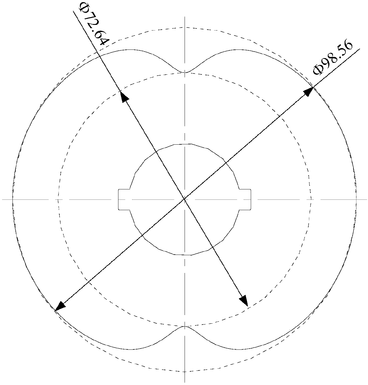
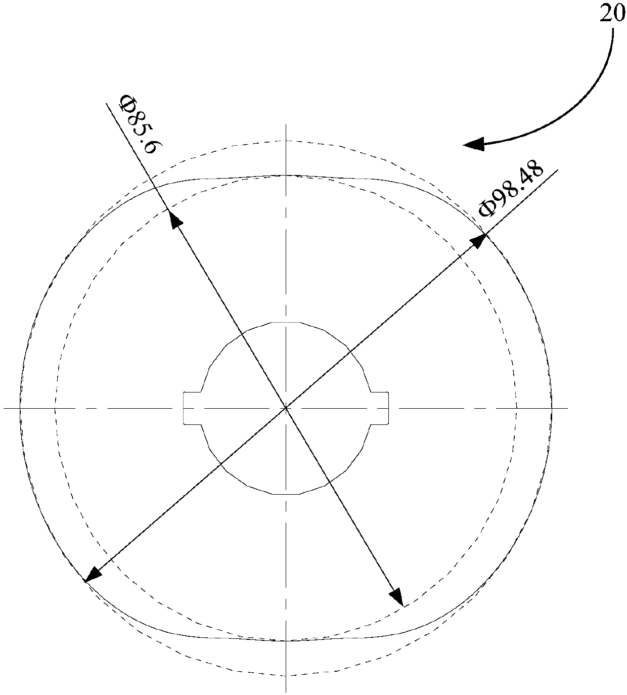
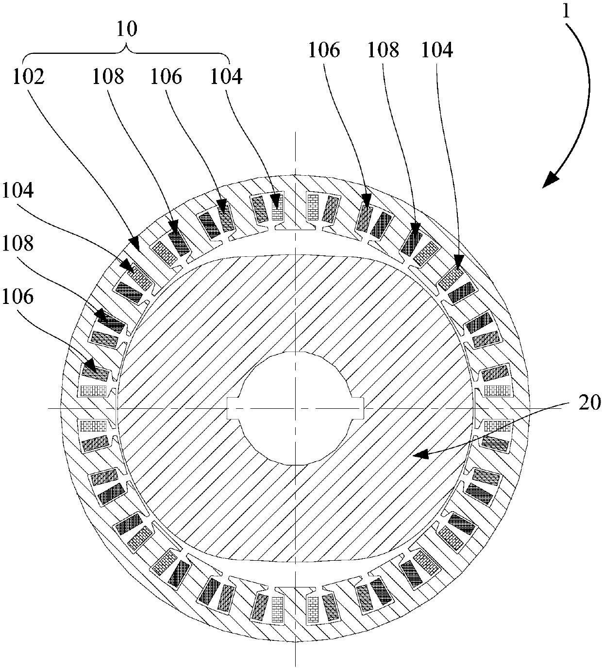
[0047] Refer below figure 2 and image 3 A resolver according to some embodiments of the present invention is described.

[0048] Such as figure 2 and image 3 As shown, the rotary transformer...


PUM


Abstract

The invention provides a rotary transformer. The rotary transformer includes a stator, and the stator comprises a stator core, an input winding and an output winding, wherein the input winding and theoutput winding are wound on the stator core; the inner side wall of the stator core is provided with a plurality of stator grooves, and the stator grooves are distributed in the circumferential direction, and the two end faces of the stator core are enabled to be connected, so that stator teeth are formed between any two adjacent stator grooves, so as to perform the winding of the input winding and the output winding respectively. The rotary transformer also comprises a rotor, wherein the rotor includes a rotor core. An air gap is defined between the inner side wall of the stator iron core and the outer side wall of the rotor iron core; when the rotor rotates, the length delta of the air gap and the mechanical rotation angle theta of the rotor meet the sine function relation containing the third harmonic component in the circumferential direction, and periodic change is executed according to the function relation so as to define the appearance of the rotor iron core. According to thetechnical scheme, under the condition of the same maximum air gap and the same minimum air gap, the output signal amplitude and the position measurement precision of the rotary transformer can be improved.

Description

technical field [0001] The invention relates to the field of transformers, in particular to a rotary transformer. Background technique [0002] A resolver is an electromagnetic sensor, also known as a synchronous resolver, used to measure the angular displacement and angular velocity of a rotating object. It is composed of a stator and a rotor. The stator winding is used as the round edge of the transformer to receive the excitation voltage. The rotor winding As the secondary side of the transformer, the induced voltage is obtained through electromagnetic coupling, and because the relative position of the primary and secondary windings of the transformer changes with the angular displacement of the rotor, the output voltage changes with the angular displacement of the rotor. The voltage amplitude of the output winding has a sine and cosine function relationship with the rotor angle. [0003] Salient pole rotary transformers are widely used in occasions requiring high safety...

Claims


Application Information

Patent Timeline
IPC IPC(8): H02K24/00G01D5/20
CPCH02K24/00G01D5/2066H02K2213/03H02K2201/03
Inventor 葛笑万佳
Owner GUANGDONG WELLING AUTO PARTS CO LTD
Learn More