
Tool for contact net H-shaped steel upright welding robot

A welding robot and H-shaped steel technology, which is applied in welding equipment, auxiliary welding equipment, welding/cutting auxiliary equipment, etc., can solve problems such as unstable welding quality, poor controllability, and low welding efficiency

Pending Publication Date: 2020-01-10
CHINA RAILWAY SHENGLE BAODING ELECTRONICS CO LTD +2
View PDF0 Cites 1 Cited by
  • Summary
  • Abstract
  • Description
  • Claims
  • Application Information

AI Technical Summary

Problems solved by technology

[0002] At this stage, my country's catenary H-shaped steel pillar has formed a relatively mature production process, but because the catenary H-shaped steel pillar is a product that is welded and combined with H-shaped steel, flange bases and other additional components, its oversized Structural modeling and self-weight restrict the development of welding process automation. Most of the H-shaped steel pillars adopt artificial gas shielded welding process, resulting in many problems such as low welding efficiency, unstable welding quality, and poor controllability.
[0003] After many investigations and researches, our company found that the existing supporting tooling for welding robots cannot meet the structural modeling and welding requirements of the oversized H-shaped steel pillars of the catenary. The structure of the welding robot, it is very important to develop a tooling for the welding robot so that the welding robot can automatically weld the H-shaped steel pillar of the catenary

Method used


Image

  • Tool for contact net H-shaped steel upright welding robot
  • Tool for contact net H-shaped steel upright welding robot
  • Tool for contact net H-shaped steel upright welding robot

Examples


Embodiment Construction

[0024] The present invention will be further described below in conjunction with the accompanying drawings and specific embodiments.

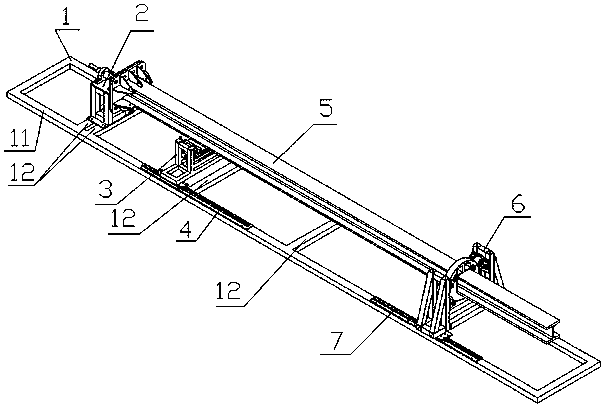
[0025] like Figure 1 to Figure 10 As shown, this embodiment includes a base 1 , a steel column welding base 2 , a steel column rotation positioning mechanism 6 and a steel column alignment and positioning mechanism 3 .

[0026] Preferably, the base 1 includes rectangular frames 11 and support ribs 12 fixed between the rectangular frames 11 .

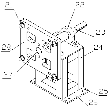
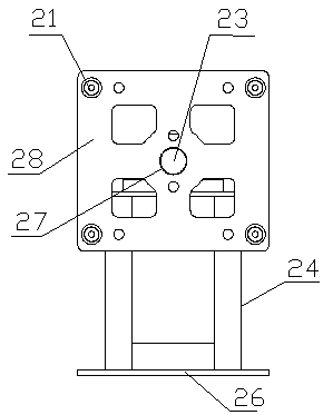
[0027] The steel column welding base 2 includes a bottom plate 26 with mounting holes 25 on both edges, a support seat 24 fixed on the bottom plate 26, two bearing seats 22 on the concentric axis fixed on the support seat 24, and two bearing seats 22 fixed on the support seat 22. The main shaft 23 and the rectangular chassis fixing plate 28 of the H-shaped steel pillar inside. The bottom plate 26 is fixed on the left end of the base 1 ; preferably, the bottom plate 26 is fixed on the support rib 12 at ...


PUM


Abstract

The invention discloses a tool for a contact net H-shaped steel upright welding robot. The tool comprises a base, a steel upright welding base, a steel upright rotation positioning mechanism and a steel upright alignment positioning mechanism; the steel upright welding base is fixed to the left end of the base, and the steel upright rotation positioning mechanism and the steel upright alignment positioning mechanism are slidingly clamped to two pair of linear guide rails, close to the right end of the steel upright welding base, of the right and left ends of the base respectively; a chassis ofan H-shaped steel upright is installed on a chassis fixing plate of the steel upright welding base in a positioning mode, and the top of the H-shaped steel upright is clamped into a supporting grooveof a clamping disc of the steel upright rotation positioning mechanism directly or through one or more spacers; when the H-shaped steel upright is installed, a steel upright supporting plate of a lifting supporting system of the steel upright alignment positioning mechanism abuts against the lower end of the H-shaped steel upright, and during welding, the steel upright supporting plate descends to the position which does not influence overturning of the H-shaped steel upright. By adopting the tool, the H-shaped steel upright can be automatically welded through the welding robot, the welding efficiency is high, the welding quality is stable, and the controllability is high.

Description

technical field [0001] The invention relates to a tooling for a robot for welding an H-shaped steel pillar of a catenary. Background technique [0002] At this stage, my country's catenary H-shaped steel pillar has formed a relatively mature production process, but because the catenary H-shaped steel pillar is a product that is welded and combined with H-shaped steel, flange bases and other additional components, its oversized Structural modeling and self-weight restrict the development of welding process automation. Most of the H-shaped steel pillars adopt artificial gas shielded welding process, resulting in many problems such as low welding efficiency, unstable welding quality, and poor controllability. [0003] After many investigations and researches, our company found that the existing supporting tooling for welding robots cannot meet the structural modeling and welding requirements of the oversized H-shaped steel pillars of the catenary. For the structure of the weldi...

Claims


Application Information

Patent Timeline
IPC IPC(8): B23K37/04
CPCB23K37/0443B23K37/0461B23K2103/04
Inventor 徐伟超张帆商顺超方和李建东宁青山郎唯博牛江辉刘旭映马慧洁刘涛梁岩张磊段玉博皮春凯周永强
Owner CHINA RAILWAY SHENGLE BAODING ELECTRONICS CO LTD
Learn More