Device for grinding building decorative plate

A decorative plate and grinding mechanism technology, which is applied to machine tools suitable for grinding workpiece planes, grinding drive devices, and parts of grinding machine tools, etc., can solve the problem that the grinding quality cannot be guaranteed, the grinding efficiency is low, and the labor intensity of operators is high. and other problems, to achieve the effect of improving grinding efficiency, reducing labor intensity and ensuring grinding quality

Inactive Publication Date: 2020-01-10
徐州华裕建筑科技有限公司
View PDF5 Cites 0 Cited by
  • Summary
  • Abstract
  • Description
  • Claims
  • Application Information

AI Technical Summary

Problems solved by technology

[0002] In the process of installing building decorative panels, it is necessary to grind the edges of the decorative panels to facilitate installation. At the same time, in order to achieve an aesthetic effect, most of the existing grinding devices need to be carried out by hand. This method is not only labor-intensive for operators. The strength is high, and the grinding efficiency is low, and the grinding quality cannot be guaranteed

Method used


Image

  • Device for grinding building decorative plate

Examples


Embodiment Construction

[0013] The present invention will be further described below in conjunction with accompanying drawing.

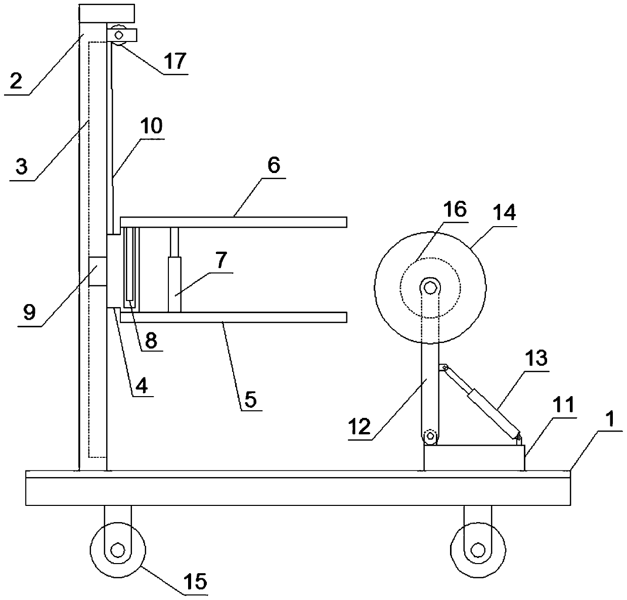
[0014] Such as figure 1 As shown, a device for grinding building decorative panels includes a support platform 1, a support clamping mechanism arranged on the upper left side of the support platform 1, and a grinding mechanism on the upper right side;

[0015] The supporting and clamping mechanism includes a vertical beam 2 fixedly connected to the upper end surface of the supporting platform 1, a winch 17 installed on the right side of the upper end of the vertical beam 2 and a clamping unit arranged on the right side of the vertical beam 2; the vertical beam 2 The right side is provided with a longitudinally extending chute 3;

[0016] The clamping unit includes a vertical beam 4, a lower clamping plate 5 vertically fixedly connected to the right side of the lower end of the vertical beam 4, an upper clamping plate 6 matched with the lower clamping plate 5, and a lifting...


PUM


Abstract

The invention relates to a device for grinding a building decorative plate. The device is characterized in that a supporting clamping mechanism comprises a vertical beam, a winch and a clamping unit,wherein the vertical beam is fixedly connected to the upper end face of a supporting platform, and the winch is mounted on the right side face of the upper end of the vertical beam; a sliding groove is formed in the right side face of the vertical beam; the clamping unit comprises a standing beam, a lower clamping plate, an upper clamping plate and a lifting hydraulic cylinder, wherein the lower clamping plate is fixedly connected to the right side of the lower end of the standing beam, and the upper clamping plate is matched with the lower clamping plate; an accommodating cavity is formed inthe longitudinal direction of the standing beam, a sliding rod is fixedly connected to the lower portion of the left end of the upper clamping plate, the sliding rod is arranged in the containing cavity in a sliding mode, and the two ends of the lifting hydraulic cylinder are fixedly connected with the upper clamping plate and the lower clamping plate correspondingly; the left end of the standingbeam is connected with a sliding block slidably arranged in the sliding groove, and the upper portion of the standing beam is connected with a steel wire rope on the winch; and a grinding mechanism comprises a bearing platform arranged on the right side of the upper end face of the supporting platform, a swing arm support hinged to the left part of the upper end face of the bearing table, a driving hydraulic cylinder with the two ends being hinged to the swing arm support and the bearing platform and a grinding roller rotationally connected to the upper end of the swing arm support. The devicefor grinding the building decorative plate has the advantages of being high in grinding efficiency and good in grinding quality.

Description

technical field [0001] The invention relates to building decoration processing equipment, in particular to a device for polishing building decoration boards. Background technique [0002] In the process of installing building decorative panels, it is necessary to grind the edges of the decorative panels to facilitate installation. At the same time, in order to achieve an aesthetic effect, most of the existing grinding devices need to be carried out by hand. This method is not only labor-intensive for operators. The strength is high, and the grinding efficiency is low, and the grinding quality cannot be guaranteed. Contents of the invention [0003] Aiming at the above-mentioned problems in the prior art, the present invention provides a device for grinding building decorative panels, which can effectively reduce the labor intensity of operators, improve the grinding efficiency, and ensure the grinding quality. [0004] In order to achieve the above object, the present inv...

Claims


Application Information

Patent Timeline
Patent Type & Authority Applications(China)
IPC IPC(8): B24B7/10B24B41/06B24B47/20B24B47/22
CPCB24B7/10B24B41/06B24B47/20B24B47/22
Inventor 张贻飞
Owner 徐州华裕建筑科技有限公司
Why Eureka
Try Eureka