Chamfering device for disc-shaped workpiece

A chamfering device, disk-shaped technology, applied in the direction of machine tools, grinding workpiece supports, grinding drive devices, etc. suitable for grinding the edge of workpieces, can solve the problems of limited use and achieve a high degree of automation

Pending Publication Date: 2020-01-10
湖南恒裕汽车零部件有限公司
View PDF0 Cites 1 Cited by
  • Summary
  • Abstract
  • Description
  • Claims
  • Application Information

AI Technical Summary

Problems solved by technology

[0004] The object of the present invention is: in order to solve the problem that most traditional chamfering devices can only chamfer workpieces of the same specification and are relatively limited in use, a chamfering device for disc-shaped workpieces is proposed

Method used


Image

  • Chamfering device for disc-shaped workpiece
  • Chamfering device for disc-shaped workpiece
  • Chamfering device for disc-shaped workpiece

Examples


Embodiment 1

[0035] see Figure 1-5 , a chamfering device for a disc-shaped workpiece, comprising an operating table 1 and a grinding mechanism 2, the operating table 1 is arranged in the shape of a "mouth", the inner cavity of the operating table 1 is provided with a turntable 11, and the rotating table 11 is fixed on the operating table 1 The output shaft of the first motor 9 on the lower table wall is connected by transmission. The output shaft of the first motor 9 can drive the turntable 11 to rotate. The upper position is adjusted. A limit mechanism 5 is provided between the moving mechanism 6 and the console 1. The limit mechanism 5 is used to clamp and fix the workpiece. Both sides of the bottom of the moving mechanism 6 are equipped with a hydraulic rod 8 and an adjusting mechanism. 3 and the grinding mechanism 2, the adjusting mechanism 3 is used to adjust the grinding angle of the grinding mechanism 2 to meet different usage requirements.

Embodiment 2

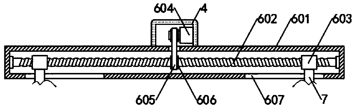
[0037] see figure 1 and Figure 5 , the moving mechanism 6 includes a fixed housing 601, the inner cavity of the fixed housing 601 is provided with a second threaded rod 602 in the horizontal direction, and the second threaded rod 602 is connected to the inner surface walls on both sides of the fixed housing 601 through bearings. , the outside of the second threaded rod 602 is screwed with two second threaded sleeves 603, the second threaded rod 602 is a two-way thread, the two second threaded sleeves 603 are arranged symmetrically about the center of the second threaded rod 602, the second threaded During the rotation of the rod 602, the two second threaded sleeves 603 approach or move away from the center of the second threaded rod 602 at the same time. The lower surface wall of the second threaded sleeve 603 is fixed with the first connecting rod 7, and the first connecting rod 7 The through groove 607 opened through the lower surface wall of the fixed housing 601 extends ...

Embodiment 3

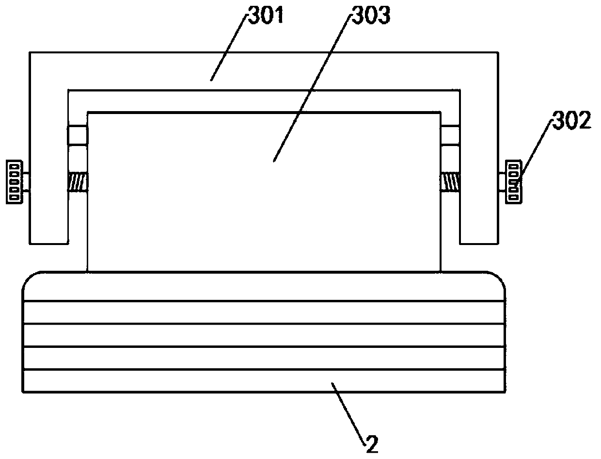
[0039] see figure 1 and image 3 , the adjustment mechanism 3 is arranged between the hydraulic rod 8 and the grinding mechanism 2, the adjustment mechanism 3 includes an inverted U-shaped connecting frame 301, the connecting frame 301 is fixed on the telescopic end of the hydraulic rod 8, and the inner wall of the connecting frame 301 rotates through a rotating shaft. plate 303, the grinding mechanism 2 is fixed on the lower surface wall of the rotating plate 303, the hydraulic rod 8 can drive the connecting frame 301 and the grinding mechanism 2 to move in the vertical direction, and the front and rear end inner walls of the connecting frame 301 are all provided with arc-shaped slides. Groove 304, two chute 304 are all provided with locking bolt 302 and locking bolt 302 and the front and rear surface wall of rotating plate 303 are screwed connection, and locking bolt 302 can slide in the inside of chute 304, and locking bolt The diameter of the end portion of 302 is greater...


PUM


Abstract

The invention discloses a chamfering device for a disc-shaped workpiece. The chamfering device comprises an operation table and a grinding mechanism. The operation table is arranged in a square shape.The inner cavity of the operation table is provided with a rotary table which is in transmission connection with an output shaft of a first motor fixed on the lower surface wall of the operation table. According to the invention, through the arrangement of a second motor, a belt pulley, and a belt, a second threaded rod can rotate. During the rotation of the second threaded rod, a second threadedsleeve can enable an adjusting mechanism and the grinding mechanism to move horizontally through a first connecting rod, so that workpieces of different diameters are chamfered. The arrangement of ahydraulic rod allows the adjusting mechanism and the grinding mechanism to move vertically, so that workpieces of different thicknesses are ground. The device has a higher degree of automation, and isconvenient for operators to use.

Description

technical field [0001] The invention relates to the technical field of chamfering devices, in particular to a chamfering device for disc-shaped workpieces. Background technique [0002] In the process of mechanical production and processing, it is necessary to chamfer the disc-shaped workpiece. The traditional chamfering method is to chamfer the workpiece through the chamfering device. With the gradual development of my country's industry, more and more manufacturers of chamfering devices , The degree of automation of the chamfering device is constantly improving. [0003] However, there are still many deficiencies in the use of chamfering devices currently on the market. For example, most traditional chamfering devices can only chamfer workpieces of the same specification, which is relatively limited in use. Therefore, It is meaningful to develop a chamfering device that can chamfer workpieces of different specifications. Contents of the invention [0004] The object of ...

Claims


Application Information

Patent Timeline
Patent Type & Authority Applications(China)
IPC IPC(8): B24B9/00B24B41/06B24B47/12B24B47/22B24B41/02
CPCB24B9/00B24B41/02B24B41/06B24B47/12B24B47/22
Inventor 钱吉治何林芳廖庆云潘桔生
Owner 湖南恒裕汽车零部件有限公司
Why Eureka
Try Eureka