
Rail current collecting device, rail vehicle bogie and power supply rail

A technology for power supply rails and current receiving devices, which is applied to bogies, power rails, vehicle components, etc., can solve the problems of poor applicability of rails, and achieve the effects of reducing production and preparation costs, simplifying rail structure, and strong applicability

Inactive Publication Date: 2020-01-10
CRRC QINGDAO SIFANG CO LTD
View PDF6 Cites 5 Cited by
  • Summary
  • Abstract
  • Description
  • Claims
  • Application Information

AI Technical Summary

Problems solved by technology

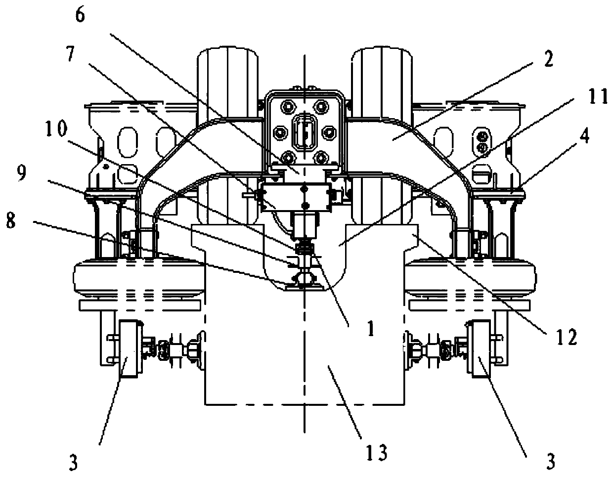
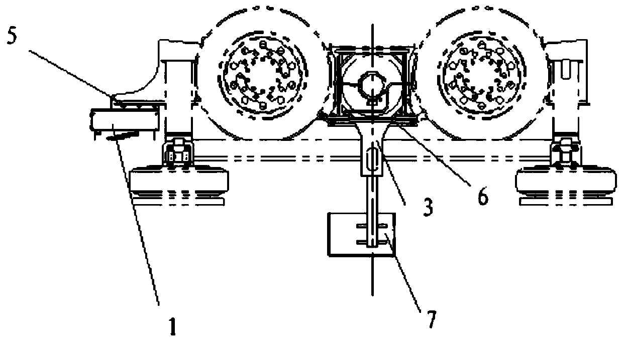
[0005] One of the objectives of the present invention is to provide a track current receiving device, a rail vehicle bogie and a power supply track to solve the problem of poor applicability of the straddle-type monorail vehicle bogie and the track in the prior art

Method used


Image

  • Rail current collecting device, rail vehicle bogie and power supply rail
  • Rail current collecting device, rail vehicle bogie and power supply rail

Examples


Embodiment Construction

[0023] Embodiments of the present invention will be further described in detail below in conjunction with the accompanying drawings and examples. The following examples are used to illustrate the present invention, but should not be used to limit the scope of the present invention.

[0024] In the description of the present invention, it should be noted that the terms "center", "longitudinal", "transverse", "upper", "lower", "front", "rear", "left", "right", " The orientations or positional relationships indicated by "vertical", "horizontal", "top", "bottom", "inner" and "outer" are based on the orientations or positional relationships shown in the drawings, and are only for the convenience of describing the present invention and Simplified descriptions, rather than indicating or implying that the device or element referred to must have a particular orientation, be constructed and operate in a particular orientation, and thus should not be construed as limiting the invention. ...


PUM


Abstract

The invention relates to the technical field of rail circuit design, and provides a rail current collecting device, a rail vehicle bogie and a power supply rail. The rail current collecting device comprises the power supply rail and current collectors in contact with the power supply rail, a straddle-type monorail comprises a straddle-type monorail body, a first electrode and second electrodes, wherein the first electrode and the second electrodes are fixed to the straddle-type monorail body, the first electrode extends out of the upper surface of the straddle-type monorail body, the second electrodes extend out of the side surface of the straddle-type monorail body and are symmetrically distributed on the two sides of the first electrode, and the current collectors comprise an upper current collector in electrical contact with the first electrode, and two lower current collectors in electrical contact with the second electrodes located on two sides correspondingly. The rail current collecting device, the rail vehicle bogie and the power supply rail are high in applicability, and the power supply requirement of the rail vehicle can be met regardless of the driving direction of therail vehicle; and in addition, for a rail vehicle needing to be turned on, the rail collecting device can simplify the required rail structure and reduce the production and preparation cost.

Description

technical field [0001] The invention relates to the technical field of track circuit design, in particular to a track current receiving device, a track vehicle bogie and a power supply track. Background technique [0002] With the development of straddle-type monorail vehicles, many medium-sized cities need to build a straddle-type monorail transportation system that combines the advantages of subways and can realize the integration of urban and suburban areas. Therefore, it is necessary to develop a new type of straddle-type monorail vehicle bogie that can meet the elevated lines in the suburbs and enter the tunnel lines in the urban area, and meet the shield tunneling requirements of the A-type subway tunnel, with a maximum speed of 100 kilometers per hour. [0003] At present, the current collectors of the straddle-type monorail vehicle bogie are arranged on both sides of the bogie frame, one of which is in contact with the positive electrode on one side of the track, and...

Claims


Application Information

Patent Timeline
Patent Type & Authority Applications(China)
IPC IPC(8): B60L5/39B60M1/30B61F5/50B61C9/50
CPCB60L5/39B60M1/30B61C9/50B61F5/50
Inventor 沙承玉赵伟王石张月军韩文峰
Owner CRRC QINGDAO SIFANG CO LTD
Learn More