
Flow accurate controlled buoyancy adjusting system

A buoyancy adjustment and precise control technology, applied in the field of ship systems, can solve problems such as accurate measurement, errors, and influence on flow accuracy measurement and control, and achieve the effects of reducing complexity, precise control, and avoiding measurement errors

Active Publication Date: 2020-01-10
BEIJING RES INST OF PRECISE MECHATRONICS CONTROLS
View PDF9 Cites 4 Cited by
  • Summary
  • Abstract
  • Description
  • Claims
  • Application Information

AI Technical Summary

Problems solved by technology

[0003] It is the most convenient and direct method to measure the flow rate through a flow meter, but the existing technology or scheme cannot accurately measure the volume of hydraulic oil flowing through the flow meter. There will inevitably be errors in the calculation of the total flow, which will affect the measurement and control of the flow accuracy; other solutions can also be used to improve the flow measurement accuracy in the existing technology, such as adding a control closed loop or using precision cylinders and sensors to measure the distribution of hydraulic oil flow , but this will greatly increase the complexity and cost of the system, thereby reducing the reliability and competitiveness of the system

Method used


Image

  • Flow accurate controlled buoyancy adjusting system
  • Flow accurate controlled buoyancy adjusting system

Examples


Embodiment Construction

[0022] Exemplary embodiments of the present disclosure will be described in more detail below with reference to the accompanying drawings. Although exemplary embodiments of the present disclosure are shown in the drawings, it should be understood that the present disclosure may be embodied in various forms and should not be limited by the embodiments set forth herein. Rather, these embodiments are provided for more thorough understanding of the present disclosure and to fully convey the scope of the present disclosure to those skilled in the art. It should be noted that, in the case of no conflict, the embodiments of the present invention and the features in the embodiments can be combined with each other. The present invention will be described in detail below with reference to the accompanying drawings and examples.

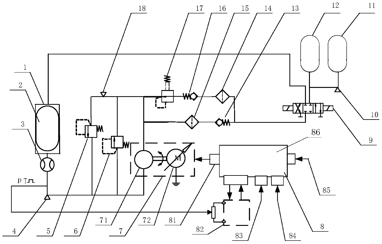
[0023] figure 1 It is a block diagram of a buoyancy adjustment system with precise flow control provided by an embodiment of the present invention. Such as ...


PUM


Abstract

The invention discloses a flow accurate controlled buoyancy adjusting system. The flow accurate controlled buoyancy adjusting system comprises a supercharged oil tank, a supercharging airbag, a gear flow meter, a first safety valve, a second safety valve, a bidirectional motor pump, a control driver, a three-position three-way electromagnetic switch valve, a first oil sac, a second oil sac, a first one-way valve, a first filter, a second filter, a second one-way valve and a pressure reducing valve, wherein the supercharging airbag is arranged in the supercharged oil tank; one end of the gear flow meter is connected with the supercharged oil tank, and the other end of the gear flow meter is connected with one oil port of the bidirectional motor pump; the other oil port of the bidirectionalmotor pump is connected with two parallel pipes; and the two parallel pipes are combined to be connected with one end of the three-position three-way electromagnetic switch valve, the second end of the three-position three-way electromagnetic switch valve is connected with the second oil sac, and the third end of the three-position three-way electromagnetic switch valve is connected with the firstoil sac. The flow accurate controlled buoyancy adjusting system conducts accurate metering on flow through the flow meter so that the flow of the system can be accurately controlled.

Description

technical field [0001] The invention belongs to the technical field of ship systems, in particular to a buoyancy adjustment system with precise flow control. Background technique [0002] The buoyancy adjustment system can be used for buoyancy balance or center of gravity adjustment of underwater vehicles, etc., which can be realized by the controllable weight change or volume change of the fluid medium. The distribution control accuracy of the fluid medium affects the overall accuracy and practicability of the buoyancy adjustment system. Key points and difficult points. [0003] It is the most convenient and direct method to measure the flow rate through a flow meter, but the existing technology or scheme cannot accurately measure the volume of hydraulic oil flowing through the flow meter. There will inevitably be errors in the calculation of the total flow, which will affect the measurement and control of the flow accuracy; other solutions can also be used to improve the ...

Claims


Application Information

Patent Timeline
IPC IPC(8): B63G8/14B63G8/24F15B11/08F15B13/02F15B21/08G05D27/02
CPCB63G8/14B63G8/24F15B11/08F15B13/02F15B21/08G05D27/02
Inventor 宋满存朱熠朱凤晴牟蓬涛李国强杨晨炜
Owner BEIJING RES INST OF PRECISE MECHATRONICS CONTROLS
Learn More