
Winding rope-in angle adjusting control system and rope-in angle adjusting control method

A technology for controlling the system and rope entry angle, applied in hoisting devices, clockwork mechanisms, etc., can solve the problems of improper winding, neat arrangement, and affecting the service life of steel wire ropes, etc., so as to reduce the rope entry angle and avoid chaos rope effect

Inactive Publication Date: 2020-01-10
CHANGSHA ZHONGLIAN HENGTONG MACHINERY
View PDF8 Cites 0 Cited by
  • Summary
  • Abstract
  • Description
  • Claims
  • Application Information

AI Technical Summary

Problems solved by technology

However, due to the limitations of the equipment structure, the relative distance between the fixed pulley 10 and the reel 20 is limited within a length range and cannot be further extended.
Since the reel 20 itself has a certain length, when the wire rope is guided from the fixed pulley 10 and wound onto the reel 20 from left to right or from right to left, if the rope entry angle is too large, the wire rope cannot pass through the natural discharge. The ropes are neatly arranged on the reel 20, which will cause disordered ropes, trapped ropes, and improper winding, which will seriously affect the service life of the steel wire rope and the operation safety of the hoisting equipment.
Ideally, the rope entry angle of the steel wire rope is preferably less than 2.0°, but the existing rope entry mechanism is limited by the relative distance between the fixed pulley 10 and the drum 20, and the rope entry angle is generally above 3.0°, which cannot be guaranteed. Neat and regular arrangement of the wire ropes on the reel 20

Method used


Image

  • Winding rope-in angle adjusting control system and rope-in angle adjusting control method
  • Winding rope-in angle adjusting control system and rope-in angle adjusting control method
  • Winding rope-in angle adjusting control system and rope-in angle adjusting control method

Examples


Embodiment Construction

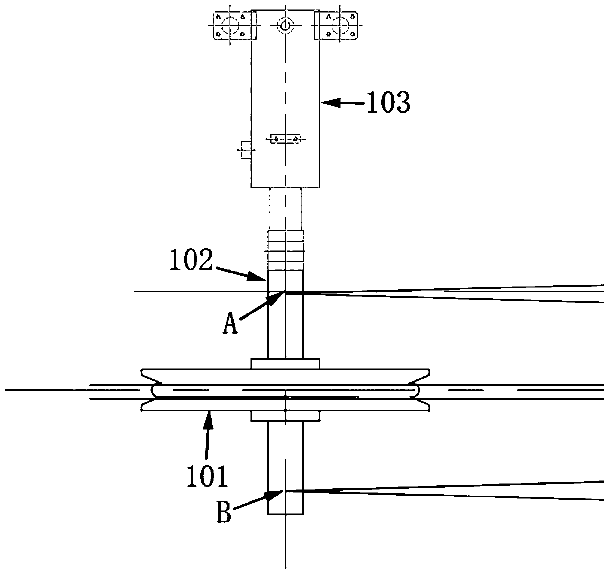
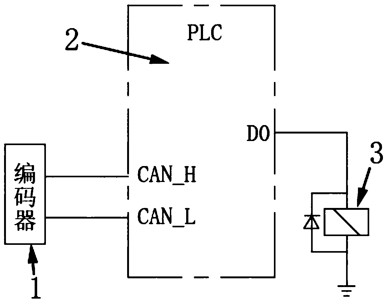
[0036] The following will clearly and completely describe the technical solutions in the embodiments of the present invention with reference to the accompanying drawings in the embodiments of the present invention. Obviously, the described embodiments are only some, not all, embodiments of the present invention. Based on the embodiments of the present invention, all other embodiments obtained by persons of ordinary skill in the art without creative efforts fall within the protection scope of the present invention.

[0037] It should be noted that, in the case of no conflict, the embodiments of the present invention and the features in the embodiments can be combined with each other.

[0038] The present invention will be further described below in conjunction with the accompanying drawings and specific embodiments, but not as a limitation of the present invention.

[0039] The hoisting rope entry angle adjustment control system provided by the embodiment of the present inventi...


PUM


Abstract

The invention discloses a winding rope-in angle adjusting control system. The winding rope-in angle adjusting control system comprises a rope-in angle adjusting mechanism and a rope-in angle adjustingcontrol system. The rope-in angle adjusting mechanism is used for adjusting the rope-in angles of steel wire ropes and guiding and winding the steel wire ropes on a winding coiling block at the angles smaller than or equal to the adjusted rope-in angles. The rope-in angle adjusting control system is in communication connection with the rope-in angle adjusting mechanism and used for controlling the rope-in angle adjusting mechanism to adjust the rope-in angles of the steel wire ropes into reasonable rope-in angles. The rope-in angles of the steel wire ropes can be reduced, thus, it is guaranteed that the steel wire ropes can be evenly and regularly arranged on the coiling block, and the phenomena that when the steel wire ropes are wound on the coiling block, rope disordering, rope sinkingand non-in-place rope winding are generated can be effectively avoided.

Description

technical field [0001] The invention relates to a hoisting rope entry angle adjustment control system, in particular to a hoisting rope entry angle adjustment control system and a rope entry angle adjustment control method. Background technique [0002] Such as Figure 7 As shown, in the prior art, the wire rope is guided to be wound on the hoisting drum 20 through a certain pulley 10 . However, due to the limitations of the equipment structure, the relative distance between the fixed pulley 10 and the reel 20 is limited within a length range and cannot be further extended. Since the reel 20 itself has a certain length, when the wire rope is guided from the fixed pulley 10 and wound onto the reel 20 from left to right or from right to left, if the rope entry angle is too large, the wire rope cannot pass through the natural discharge. The rope way is neatly arranged on the reel 20, which will cause disordered ropes, trapped ropes, and incomplete rope winding, which will seri...

Claims


Application Information

Patent Timeline
Patent Type & Authority Applications(China)
IPC IPC(8): B66D1/38
CPCB66D1/38
Inventor 梁更生谢子云陈立范志勇周科雄
Owner CHANGSHA ZHONGLIAN HENGTONG MACHINERY
Learn More