High-efficiency yarn dyeing device

A yarn dyeing and high-efficiency technology, applied in the field of dyeing equipment, can solve the problems of low economic benefit, large labor and large bath, and achieve the effects of improving dyeing efficiency, uniformity and twist balance.

Inactive Publication Date: 2020-01-10
傅全辉
View PDF0 Cites 4 Cited by
  • Summary
  • Abstract
  • Description
  • Claims
  • Application Information

AI Technical Summary

Problems solved by technology

[0003] In the traditional yarn dyeing process, the yarn is placed in the dyeing tank for bath dyeing. When dyeing in this traditional bath dyeing method, the bath is relatively large, and dyeing is easy to occur. At the same time, manual starting is required, and the uniformity of dyeing cannot be guaranteed. , resulting in a large amount of manual labor and low economic benefits

Method used


Image

  • High-efficiency yarn dyeing device
  • High-efficiency yarn dyeing device
  • High-efficiency yarn dyeing device

Examples


Embodiment 1

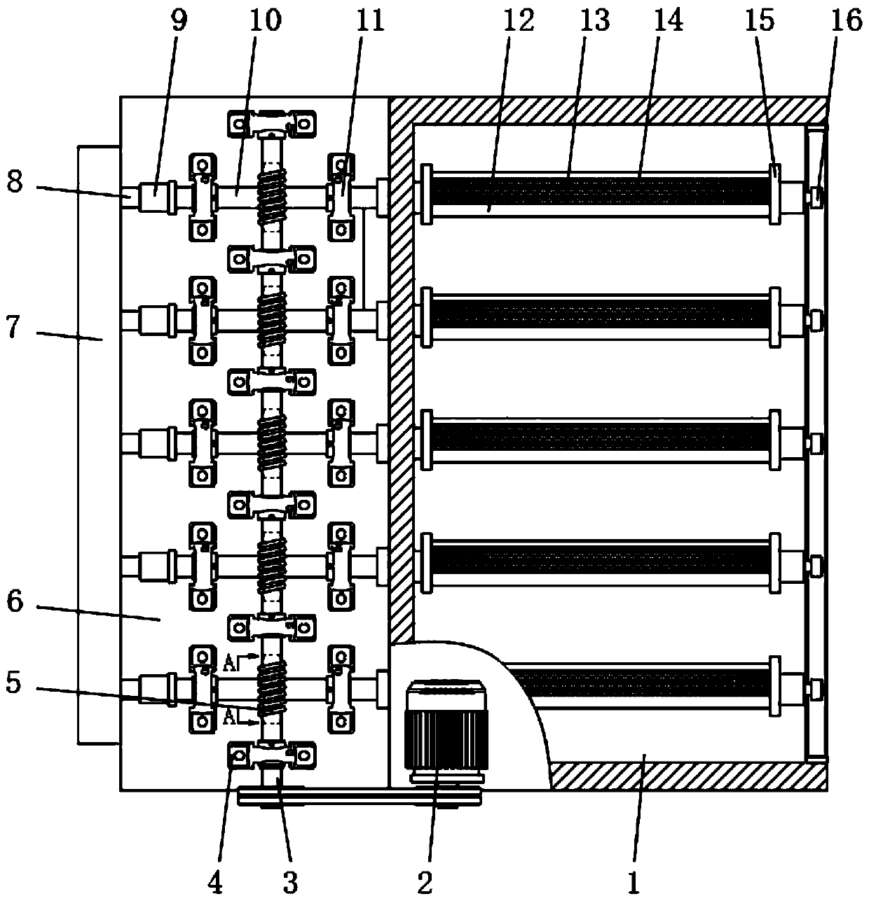
[0034] Embodiment one, with reference to figure 1 and Figure 4 , a high-efficiency yarn dyeing device, including a dyeing bin 1, a dye solution box 24 and a spray pipe 12, a driving motor 2 is installed on the dyeing bin 1, and a drive shaft is connected to one side of the driving motor 2 through a belt and a pulley. 3. The drive shaft 3 is erected on the platform 6 through the first bearing seat 4 and the bracket 17, and the drive shaft 3 is provided with a worm 5, and a worm gear 36 is connected to the bottom of the worm 5, and the worm gear 36 is installed on the hollow shaft 10, and The hollow shaft 10 is erected on the platform 6 through the second bearing seat 11. One end of the hollow shaft 10 is connected to the branch pipe 8 through the rotary joint 9, and the other end runs through the side wall of the dyeing chamber 1 to connect with the injection pipe 12. The platform 6 is located in the dyeing chamber 1. Side, and below the platform 6 is provided with a dye solu...

Embodiment 2

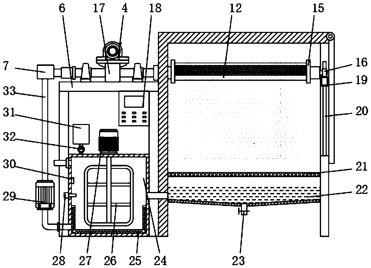
[0035] Embodiment two, refer to figure 2, a stirring motor 27 is installed on the top of the dye liquor box 24, and a stirring rod 26 is connected to the inside of the dye liquor box 24 below the stirring motor 27, and a temperature sensor 30 and a concentration detection device are respectively arranged on one side of the stirring rod 26 and located on the inner surface of the dye liquor box 24. 28, and a heating layer 25 is provided below the stirring rod 26, a stirring motor 27 is provided with a dyeing agent 31 and a flow controller 32 from top to bottom, and is connected to the dye solution tank 24, and a control panel 18 is embedded on the front surface of the platform 6 , and the control panel 18 is electrically connected to the driving motor 2, the stirring motor 27, the concentration detector 28, the circulating pump 29, the temperature sensor 30 and the flow controller 32 through the PLC controller provided inside, and the stirring is started by the control panel 18 ...

Embodiment 3

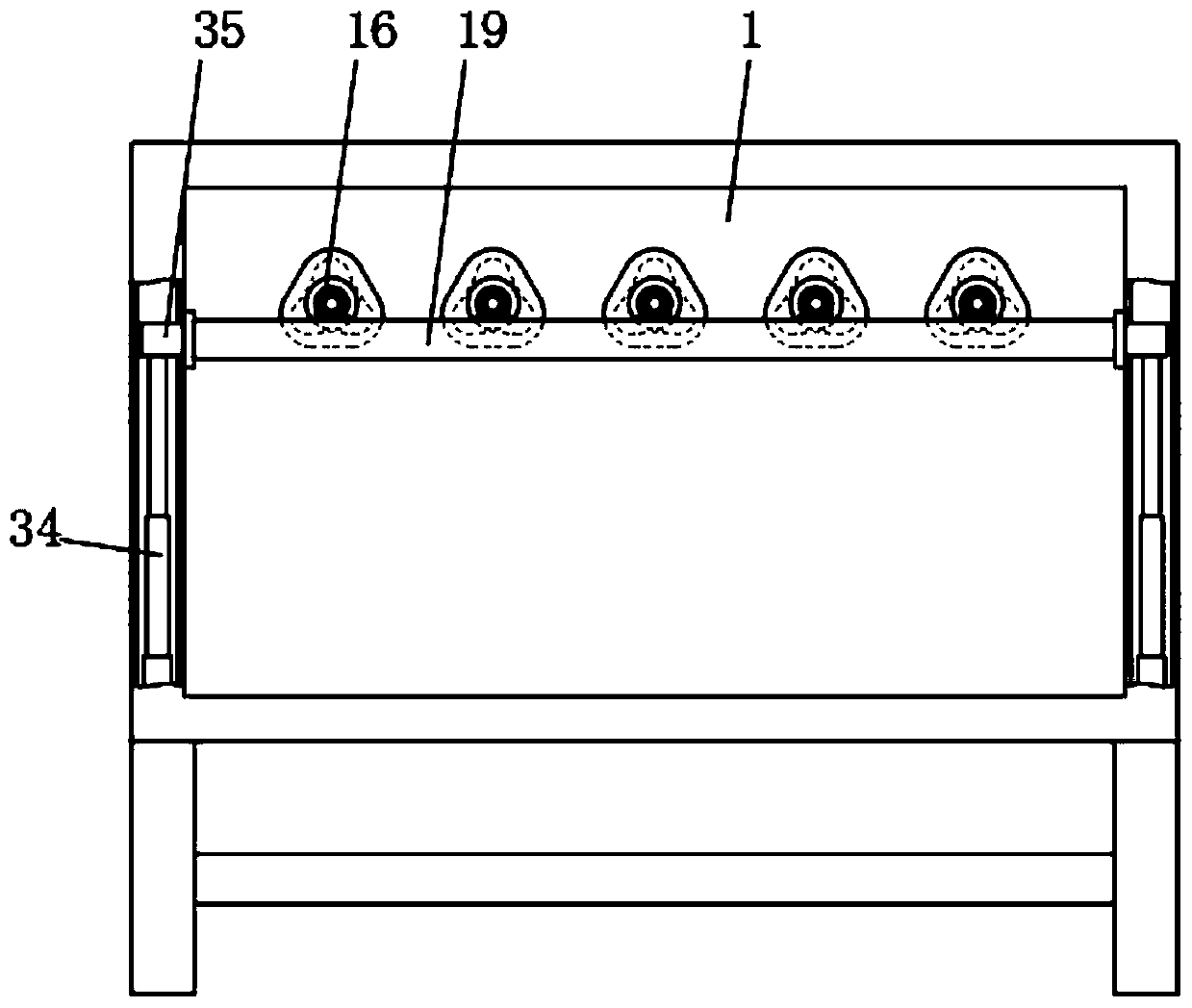
[0036] Embodiment three, refer to figure 2 and Figure 5 , a plurality of injection pipes 12 are provided, and a plurality of injection pipes 12 are evenly arranged inside the dyeing chamber 1. The inside of the injection pipe 12 is a cavity structure, and baffles 15 are welded at both ends, and a support bearing is installed on one end surface 16. The injection pipe 12 has a triangular cross-section and an arc-shaped concave surface 13 on the side. A plurality of nozzles 14 are uniformly arranged on the surface of the arc-shaped concave surface 13. One side of the dye solution tank 24 communicates with the flow divider 7 through the main pipe 33, and the main pipe 33 is installed There is a circulation pump 29, and a plurality of branch pipes 8 are arranged on one side of the flow divider 7, and each branch pipe 8 is connected to the corresponding injection pipe 12 through a rotary joint 9 and a hollow shaft 10, and a filter screen 21 is arranged under the inside of the dyei...


PUM


Abstract

The invention discloses a high-efficiency yarn dyeing device, which comprises a dyeing bin, a dyeing liquid box and spraying pipes; a driving motor is mounted on the dyeing bin, one side of the driving motor is in transmission connection with a driving shaft through a belt and a pulley, and the driving shaft is erected on a platform through a first bearing block and a bracket. In the invention, the plurality of spraying pipes for hanging yarns are arranged inside the dyeing bin; the driving shaft which is in transmission connection via the belt and the belt pulley is driven to rotate by the driving motor; a worm arranged on the driving shaft is in transmission connection with a turbine mounted on hollow shafts; the spraying pipes connected with the hollow shafts in a one-to-one correspondence mode rotate synchronously, and a dyeing liquid is sprayed onto yarns through nozzles to uniformly dye the yarns; the manner of synchronously driving multiple spraying pipes to rotate for dyeing helps improve dyeing efficiency of the device, and allows the yarns suspended on the spraying pipes to be freely untwisted until the twist is balanced, so that the tension in spinning is eliminated.

Description

technical field [0001] The invention relates to the technical field of dyeing equipment, in particular to an efficient yarn dyeing device. Background technique [0002] Yarn is a kind of textile, which is processed into a certain fineness product with various textile fibers, and is used for weaving, rope making, thread making, knitting and embroidery, etc. It is divided into staple fiber yarn, continuous filament and so on. In the production process of textiles, dyeing is carried out in the front of the weaving production process. Yarn dyeing can generally obtain a good and firm level dyeing effect, and can be woven with natural yarns according to different design requirements, thereby obtaining higher economic value and The lead time can be shortened, so the product has high reproducibility. [0003] In the traditional yarn dyeing process, the yarn is placed in the dyeing tank for bath dyeing. When dyeing in this traditional bath dyeing method, the bath is relatively large...

Claims


Application Information

Patent Timeline
Patent Type & Authority Applications(China)
IPC IPC(8): D06B5/16D06B23/20D06B23/22
CPCD06B5/16D06B23/20D06B23/205D06B23/22
Inventor 傅全辉
Owner 傅全辉
Why Eureka
Try Eureka