Discontinuous coherence-based InSAR earth surface deformation monitoring method and system

A technology of surface deformation and deformation, which is applied in the field of microwave remote sensing, can solve the problems of not considering, reducing the coherence of interferograms, and less point distribution in low coherence areas.

Active Publication Date: 2020-01-10
CHINA UNIV OF GEOSCIENCES (BEIJING)
View PDF9 Cites 7 Cited by
  • Summary
  • Abstract
  • Description
  • Claims
  • Application Information

AI Technical Summary

Problems solved by technology

However, this method can only monitor areas that maintain high coherence in the time series, such as urban areas, exposed rocks, and large man-made facilities.
It is invalid for low coherence value areas (vegetation), which cannot completely reflect the deformation area, which makes it difficult for subsequent deformation interpretation
Due to the influence of human activities, geological activities and geological environment, such as seasonal vegetation coverage, soil moisture and climate change, etc., the physical characteristics of the surface will be suddenly changed, reducing the coherence of the interferogram, causing these pixels to be interrupted in the time series Coherence, although such points contain deformation information in the time series, they are not considered in the traditional SBAS technology, so that the distribution of points in low coherence areas is less, so that the deformation information in these areas cannot be correctly reflected

Method used


Image

  • Discontinuous coherence-based InSAR earth surface deformation monitoring method and system
  • Discontinuous coherence-based InSAR earth surface deformation monitoring method and system
  • Discontinuous coherence-based InSAR earth surface deformation monitoring method and system

Examples


Embodiment Construction

[0056] The following will clearly and completely describe the technical solutions in the embodiments of the present invention with reference to the accompanying drawings in the embodiments of the present invention. Obviously, the described embodiments are only some, not all, embodiments of the present invention. Based on the embodiments of the present invention, all other embodiments obtained by persons of ordinary skill in the art without making creative efforts belong to the protection scope of the present invention.

[0057] The purpose of the present invention is to provide an InSAR surface deformation monitoring method and system based on discontinuous coherence, which can effectively monitor the regional deformation of discontinuous coherence points in time series.

[0058] In order to make the above objects, features and advantages of the present invention more comprehensible, the present invention will be further described in detail below in conjunction with the accompa...


PUM


Abstract

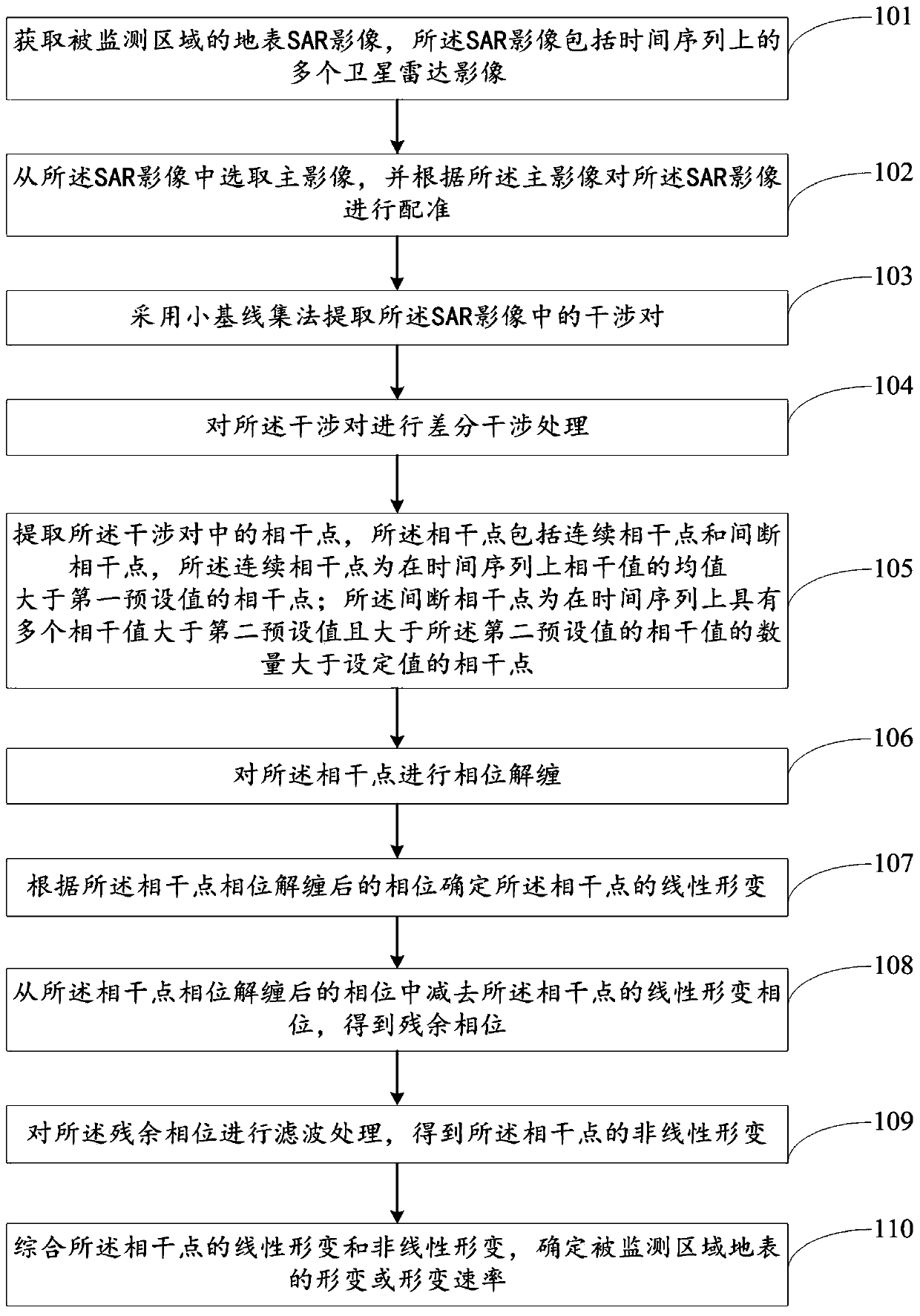
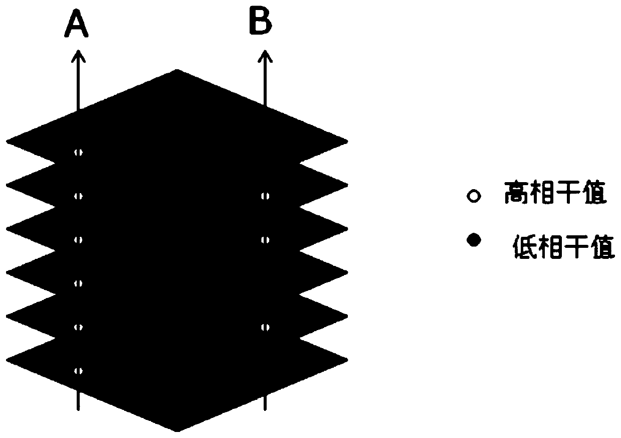
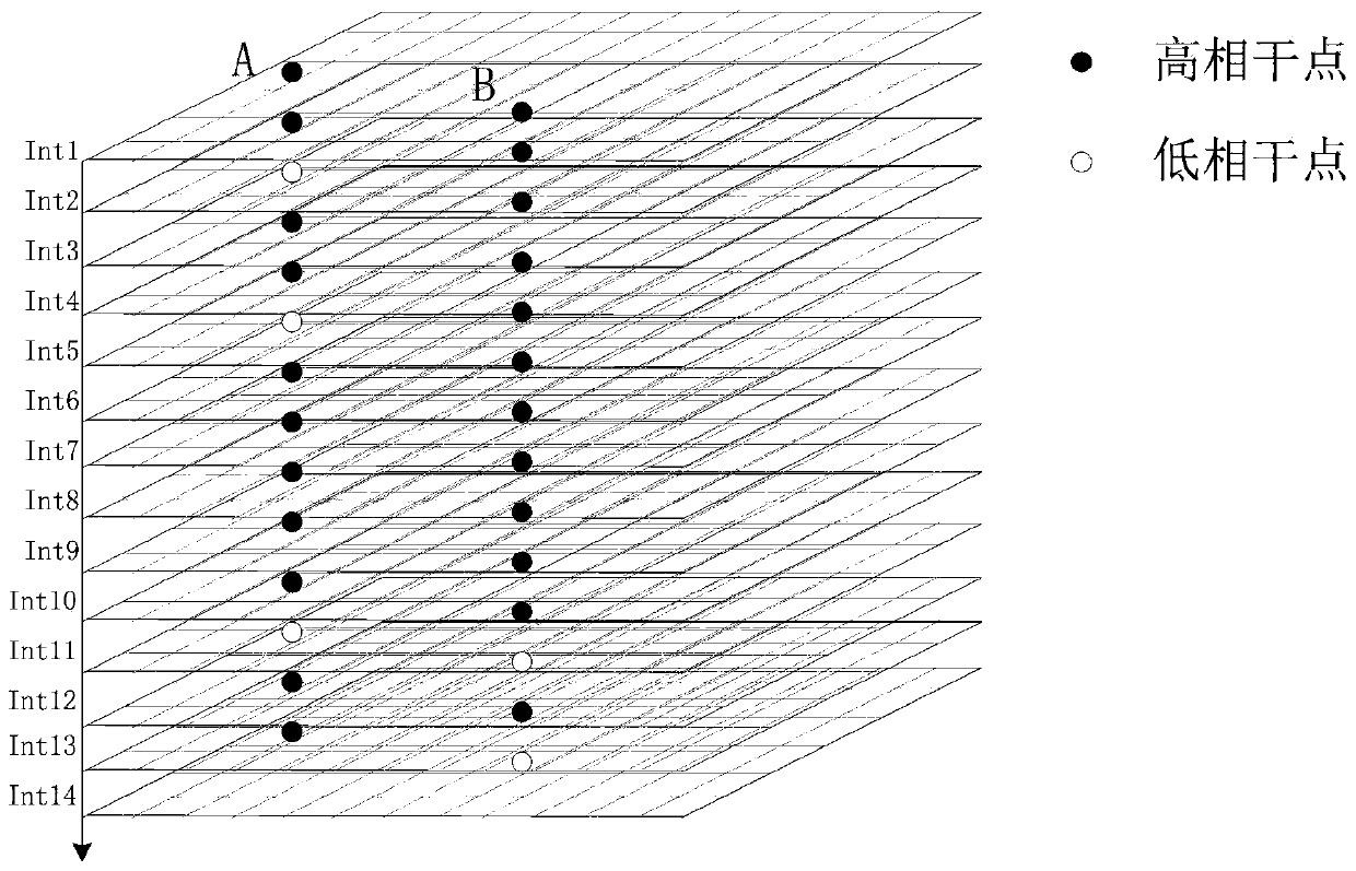
The invention discloses a discontinuous coherence-based InSAR earth surface deformation monitoring method and system. The method comprises the steps of acquiring an earth surface SAR image of a monitored region; registering the SAR image; extracting an interference pair in the SAR image by a small baseline subset method; performing differential interference processing on the interference pair; extracting a coherent point in the interference pair, wherein the coherent point comprises a continuous coherent point and a discontinuous coherent point, the high coherence of the continuous coherent point is continuously maintained on a time sequence, and the high coherence of the discontinuous coherent point is discontinuously maintained on the time sequence; performing phase unwrapping on the coherent point; determining linear deformation of the coherent point according to a phase of the coherent point after phase unwrapping; subtracting a linear deformation phase of the coherent point from the phase of the coherent point after phase unwrapping to obtain a residual phase; filtering the residual phase to obtain non-linear deformation of the coherent point; and summarizing the linear deformation and the non-linear deformation of the coherent point, and determining deformation or deformation rate of an earth surface of the monitored region. By the method, the regional deformation of discontinuous coherent point location on the time sequence can be effectively monitored.

Description

technical field [0001] The invention relates to the technical field of microwave remote sensing, in particular to an InSAR surface deformation monitoring method and system based on discontinuous coherence. Background technique [0002] InSAR is an active microwave radar detection technology. It has technical advantages such as large scale, low cost and high precision. In recent years, it has shown great potential for deformation monitoring in many fields, such as landslides, glacier movement, land subsidence, etc. The conventional Differential SAR Interferomtry (DInSAR) technology calculates the deformation by making a difference between two images, but because DInSAR technology is affected by the phenomenon of decoherence, the current research on InSAR technology in the world mainly focuses on long-term sequence DInSAR technical research. The long-time series DInSAR is significantly different from the traditional DInSAR. It mainly analyzes the points with stable phase an...

Claims


Application Information

Patent Timeline
IPC IPC(8): G01S13/90
CPCG01S13/885G01S13/9023
Inventor 杨红磊彭军还刘杰
Owner CHINA UNIV OF GEOSCIENCES (BEIJING)
Why Eureka
Try Eureka