Real-time tracking detection method for state of split knife switch

A technology of real-time tracking and detection method, applied in the field of image recognition, can solve the problem of low real-time detection accuracy of knife gate status, and achieve the effect of improving stability and positioning accuracy

Pending Publication Date: 2020-01-10
南京鑫和汇通电子科技有限公司
View PDF0 Cites 4 Cited by
  • Summary
  • Abstract
  • Description
  • Claims
  • Application Information

AI Technical Summary

Problems solved by technology

[0004] In order to solve the problem of low real-time detection accuracy of the knife switch state in the ...

Method used


Image

  • Real-time tracking detection method for state of split knife switch

Examples


Embodiment 1

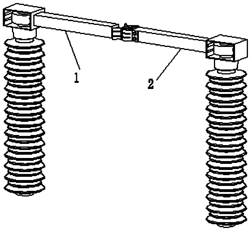
[0044] Embodiment 1: as figure 1 As shown, a real-time tracking method for detecting the state of the split knife switch, including: collecting the real-time monitoring video of the split knife switch, acquiring each frame of the video image and establishing the model of the knife switch arm according to any frame image The boundary line model is saved as a model file, and the left midpoint, right midpoint, midpoint and centerline of the knife arm are calculated according to the model file; the first frame image of the video is obtained and the knife gate is positioned, and the second The feature points of the knife arm in one frame image that are useful for tracking are recorded; according to the above positioning results, edge detection is performed on the first frame image of the video to obtain a set of edge lines, and the left edge of the left knife arm 1 in the first frame image is calculated. The distance between the midpoint and the right midpoint of the right knife ar...

Embodiment 2

[0053] Embodiment 2: On the basis of Embodiment 1, in the current frame image, the edge line set of the left knife gate arm and the edge line set of the right knife gate arm are eliminated, and according to the positioning result in the current frame image Perform edge detection on the knife gate, and determine the edge line of the left knife gate arm and the right knife gate arm edge line in the current frame image, the specific method is: obtain the edge line set of the left knife gate arm and the right knife gate The edge line set of the gate arm is obtained in the same way as the edge line set of the left knife arm and the edge line set of the right knife arm in the current frame image; traverse the edge line set of the left knife arm of the current frame image, and the left angle threshold is given, if the left If the angle of the edge line of the knife arm is greater than the sum of the estimated left knife arm angle of the current frame image and the left angle threshold...


PUM


Abstract

The invention provides a real-time tracking detection method for the state of a split knife switch. The real-time tracking detection method comprises the steps: collecting a real-time monitoring videoof the split knife switch, obtaining each frame of image of the video, building a boundary line model of a knife switch arm of the type, and storing the boundary line model as a model file; acquiringa first frame image of the video, positioning a knife switch in the first frame image, and extracting tracking feature points; performing detection according to a positioning result, and calculatingan initial included angle between the left knife switch arm and the right knife switch arm; and tracking and positioning the knife switch arm in the next frame of image, estimating a system error, determining a correction included angle between the left knife switch arm and the right knife switch arm in the next frame of image, judging the real-time state of the knife switch in the next frame of image until the knife switch is detected to stop moving, and verifying the final state of knife switch movement in the video. According to the real-time tracking detection method, the problem of low real-time detection precision of the state of the split knife switch is solved.

Description

technical field [0001] The invention relates to the technical field of image recognition, in particular to a method for detecting the state of a split knife switch with real-time tracking. Background technique [0002] Knife switch is a very frequently used electrical appliance in high-voltage switchgear, and it plays an isolation role in the circuit. In practical applications, due to the long-term operation of the switch, the switch may not close or open properly, which will cause an arc between the left and right switch arms of the switch. Arc is a gas discharge phenomenon. The instantaneous spark generated by the current passing through some insulating media may cause fire or threaten personal safety; in addition, the arc temperature is extremely high, and it is easy to burn the insulating material, causing leakage events or damage to the knife switch equipment. ; Therefore, the closed state of the knife switch needs to be accurately detected. [0003] To detect the rea...

Claims


Application Information

Patent Timeline
IPC IPC(8): G06T7/73G06T7/246G06T7/13
CPCG06T7/13G06T7/246G06T7/73G06T2207/10016G06T2207/20081G06T2207/30232
Inventor 蔡丽莎汪辉任昌胡海涛刘晶
Owner 南京鑫和汇通电子科技有限公司
Why Eureka
Try Eureka