Dynamic register, data arithmetic unit, chip, computing power board and computing device

A register and latch unit technology, applied in the field of computing power board and computing equipment, chip, data operation unit, dynamic register, can solve the problems of dynamic leakage, data loss, etc., to increase the equivalent capacitance, improve stability, enhance The effect of safety and accuracy

Pending Publication Date: 2020-01-10
HANGZHOU CANAAN INTELLIGENCE INFORMATION TECH CO LTD
View PDF0 Cites 4 Cited by
  • Summary
  • Abstract
  • Description
  • Claims
  • Application Information

AI Technical Summary

Problems solved by technology

However, nodes S0 and S1 are prone to dynamic leakage, resulting in the loss of temporarily stored data

Method used


Image

  • Dynamic register, data arithmetic unit, chip, computing power board and computing device
  • Dynamic register, data arithmetic unit, chip, computing power board and computing device
  • Dynamic register, data arithmetic unit, chip, computing power board and computing device

Examples


Embodiment 1

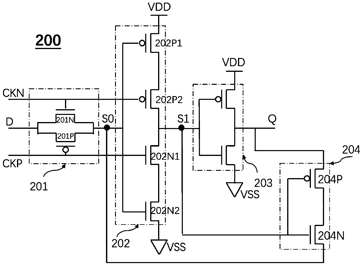
[0057] figure 2 It is a schematic diagram of the circuit structure of a dynamic register according to an embodiment of the present invention. Such as figure 2 As shown, the dynamic register 200 includes an input terminal D, an output terminal Q, a clock signal terminal CKN, a clock signal terminal CKP, a switch unit 201, a latch unit 202, an output drive unit 203, and a leakage compensation unit 204. The switch unit 201, the latch unit 202, and the output drive unit 203 are sequentially connected in series between the input terminal D and the output terminal Q. The switch unit 201 and the latch unit 202 form a first node S0, the latch unit 202 and the output drive A second node S1 is formed between the units 203. The leakage compensation unit 204 is electrically connected between the first node S0, the second node S1 and the output terminal Q. The input terminal D is used to input data, the output terminal is used to output data, the clock signal terminal CKN and the clock s...

Embodiment 2

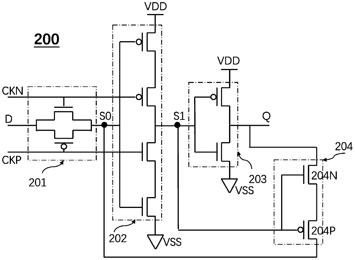
[0067] image 3 It is a schematic diagram of the circuit structure of a dynamic register according to another embodiment of the present invention. Such as image 3 As shown, the dynamic register 200 includes an input terminal D, an output terminal Q, a clock signal terminal CKN, a clock signal terminal CKP, a switch unit 201, a latch unit 202, an output drive unit 203, and a leakage compensation unit 204. The switch unit 201, the latch unit 202, and the output drive unit 203 are sequentially connected in series between the input terminal D and the output terminal Q. The switch unit 201 and the latch unit 202 form a first node S0, the latch unit 202 and the output drive A second node S1 is formed between the units 203. The leakage compensation unit 204 is electrically connected between the first node S0, the second node S1 and the output terminal Q. The input terminal D is used to input data, the output terminal is used to output data, the clock signal terminal CKN and the cloc...


PUM


Abstract

The invention provides a dynamic register, a data operation unit, a chip, a computing power board and a computing device. The dynamic register comprises an input end, an output end, a clock signal end, a switch unit, a latch unit and an output driving unit, wherein the switch unit, the latch unit and the output driving unit are sequentially connected between the input end and the output end in series, a first node is arranged between the switch unit and the latch unit, and a second node is arranged between the latch unit and the output driving unit. The dynamic register further comprises an electric leakage compensation unit, and the electric leakage compensation unit is electrically connected among the first node, the second node and the output end. According to the present invention, theequivalent capacitance of the nodes can be increased, the dynamic leakage current of the nodes is compensated, and the safety and accuracy of the data are improved.

Description

Technical field [0001] The invention relates to a storage device controlled by a clock, in particular to a dynamic register, a data operation unit, a chip, a computing power board and a computing device used in a large-scale data computing device. Background technique [0002] Dynamic registers are widely used and can be used as digital signal registers. figure 1 It is the circuit structure diagram of the existing dynamic register. Such as figure 1 As shown, the dynamic register includes a transmission gate 101, a tri-state inverter 102, and an inverter 103 connected in series between an input terminal D and an output terminal Q. A node S0 is formed between the transmission gate 101 and the three-state inverter 102, and a node S1 is formed between the three-state inverter 102 and the inverter 103. The data passes through the three-state inverter 102 and the parasitic of the transistor in the inverter 103. The capacitor temporarily exists at node S0 and / or node S1. However, node...

Claims


Application Information

Patent Timeline
Patent Type & Authority Applications(China)
IPC IPC(8): G11C19/28G06F1/20G06F1/26G06F15/16
CPCG06F1/20G06F1/26G06F15/16G11C19/28
Inventor 鲍进华张楠赓张建刘杰尧吴敬杰马晟厚
Owner HANGZHOU CANAAN INTELLIGENCE INFORMATION TECH CO LTD
Why Eureka
Try Eureka