High-voltage connector with secondary locking structure

A high-voltage connector and secondary locking technology, which is applied in the direction of connection, two-part connection device, and parts of the connection device, can solve problems such as easy rotation of cables, poor shielding contact, and uneven contact force, and achieve guaranteed The effect of connection stability, high assembly efficiency and reliable connection

Pending Publication Date: 2020-01-10
郑州赛川电子科技有限公司
View PDF0 Cites 7 Cited by
  • Summary
  • Abstract
  • Description
  • Claims
  • Application Information

AI Technical Summary

Problems solved by technology

[0004] The existing high-voltage connectors have the following disadvantages: (1) The plastic cassette is used to realize the secondary locking function, which adds a part, and the overall product is not beautiful; (2) The bellows and the high-voltage connector are connected by heat-shrinkable tubes or rubber tubes Low holding force, easy to disengage during assembly; (3) Low production efficiency of wire harness; (4) Use plug to seal cable, and the sealing reliability of high-voltage connector will decrease after working for a long time; (5) Use plug to fix cable, After the high-voltage connector works for a long time, the cable is easy to rotate or move axially; (6) The shielding crimping sleeve and the shielding ring are used to realize the conduction of the shielding, but there is no fixed position between the crimping sleeve and the shielding ring, and the shielding ring The claws are in contact with the surface or edge of the hexagonal cross-section of the crimping sleeve after crimping, the contact force is uneven, and the problem of poor shielding contact is prone to occur

Method used


Image

  • High-voltage connector with secondary locking structure
  • High-voltage connector with secondary locking structure
  • High-voltage connector with secondary locking structure

Examples


Embodiment Construction

[0031] It should be noted that the location words "front", "rear" and "end" in the present invention refer to the front of the socket part, and the back and the end of the part far away from the socket part. The socket part refers to the plug The part that is plugged into the socket.

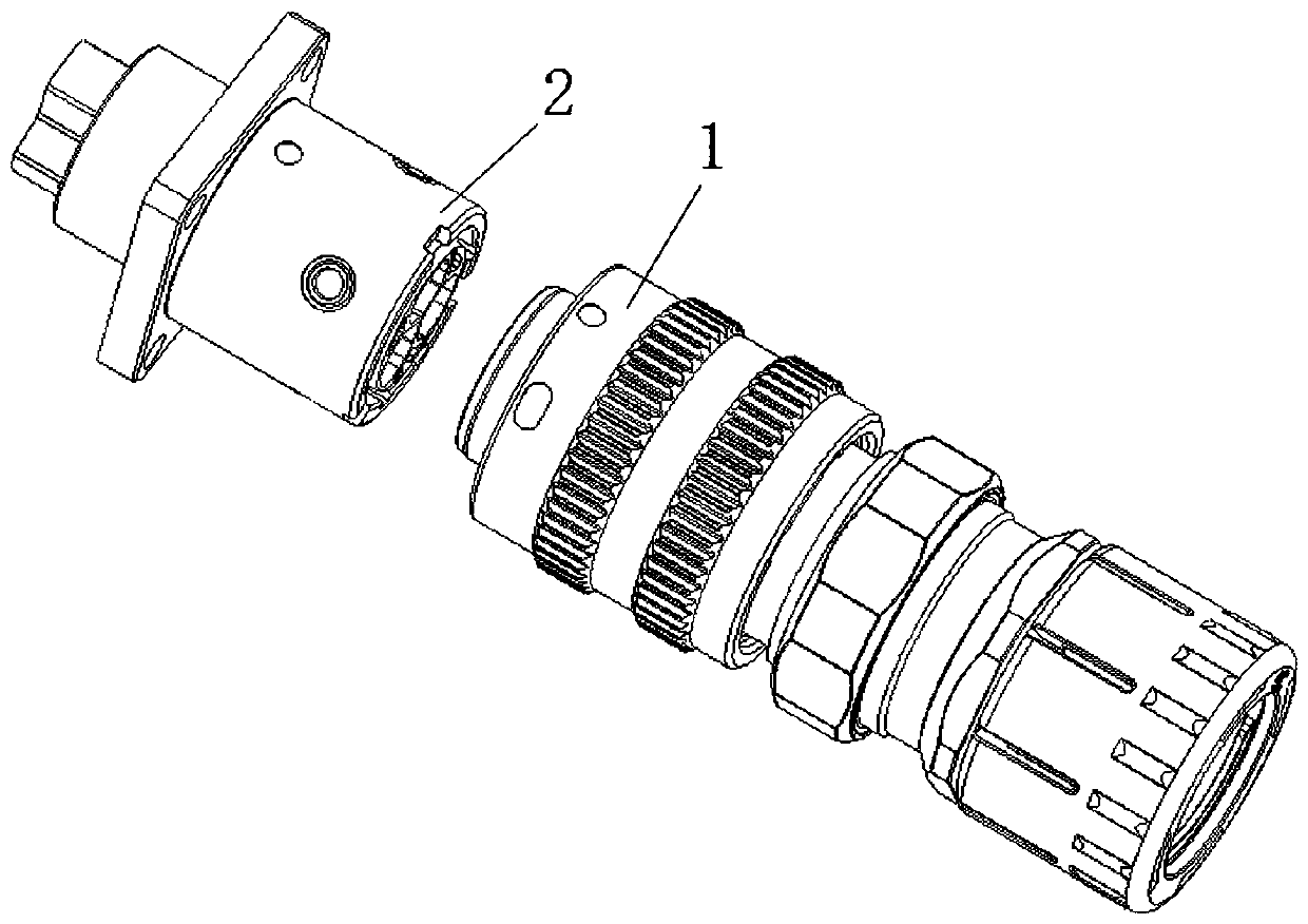
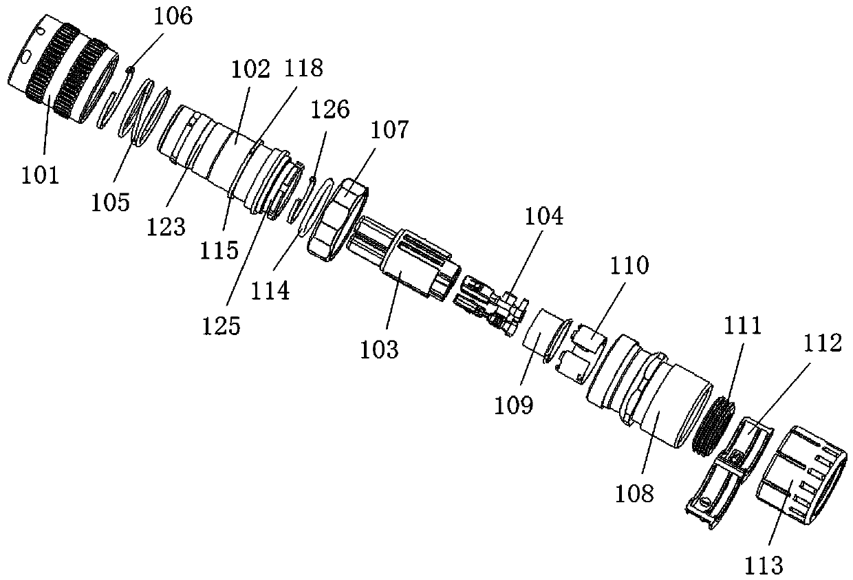
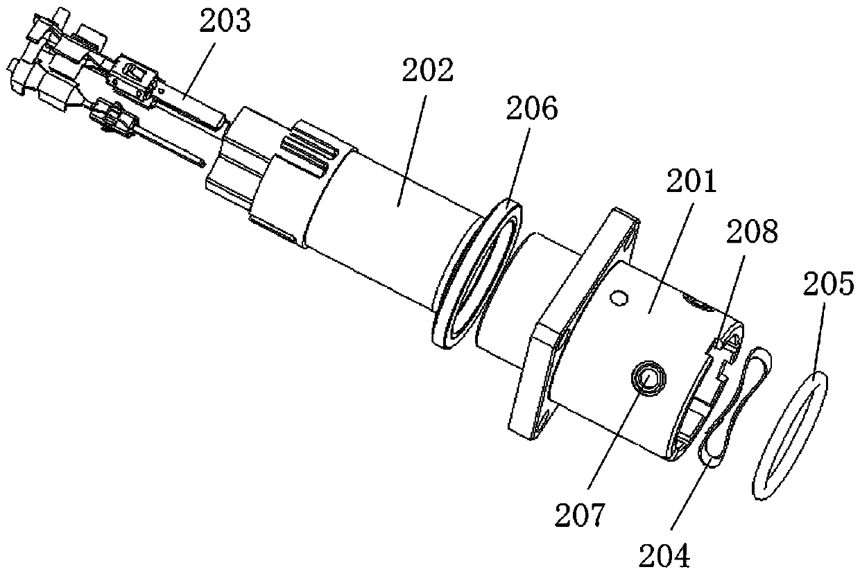
[0032] like Figure 1-14 As shown, a high-voltage connector with a secondary locking structure has a variety of key positions, small size, convenient and fast connection, and has a secondary locking structure to ensure the stability of the connection between the plug 1 and the socket 2; The effective connection with the wiring harness of the corrugated tube saves the process of winding tape or heat shrinkable tube, greatly improves the assembly efficiency, and the assembly holding force is much greater than that of tape winding or heat shrinkable tube, effectively improving the product aesthetics. The high-voltage connector with a secondary locking structure includes a plug 1 and a socket 2 mat...


PUM


Abstract

The invention discloses a high-voltage connector with a secondary locking structure. The high-voltage connector comprises a plug and a socket. The plug consists of a connecting cap, a plug shell, a plug insulator and a jack which are sequentially sleeved from outside to inside. The socket includes a socket shell, a socket insulator and a pin which are sequentially sleeved from outside to inside. At least one boss is arranged at the front end of the connecting cap; a main key groove, a short key groove and a first annular groove are formed in the rear end of the connecting cap; the first annular groove is communicated with the main key groove and the short key groove; and A groove matching the boss is formed in the end face of the socket shell. The provided high-voltage connector has advantages of different kinds of key positions, small size, and great convenient and rapidness of connection. On the basis of a secondary locking structure, the stability of connection between the plug andthe socket is ensured; effective connection with a penetrating corrugated pipe harness is realized and the procedure of adhesive tape winding or heat shrink tube winding is omitted, so that the assembly efficiency is greatly improved; and the assembly retention force is far larger than that of adhesive tape winding or heat shrink tube winding, so that the product attractiveness is effectively improved.

Description

technical field [0001] The invention belongs to the field of high-voltage connectors, in particular to a high-voltage connector with a secondary locking structure. Background technique [0002] With the development of new energy vehicle technology, the requirements for the reliability, protection level, vehicle assembly efficiency, and wiring harness production efficiency of high-voltage connectors are getting higher and higher, and the requirements for appearance beauty are also getting higher and higher. The first-generation high-voltage connector technical solution is based on the modification of connector products suitable for military, communication and other fields. It has the following shortcomings: (1) It cannot meet the requirements of secondary locking; (2) It adopts machine-added terminals , the production efficiency is low, the production efficiency of the wire harness is reduced accordingly, the terminal cannot be automatically crimped, and the corrugated tube n...

Claims


Application Information

Patent Timeline
Patent Type & Authority Applications(China)
IPC IPC(8): H01R13/627H01R13/639H01R13/58H01R13/648H01R13/502H01R13/508H01R24/00
CPCH01R13/502H01R13/508H01R13/5825H01R13/6276H01R13/639H01R13/648H01R24/00
Inventor 王鹏飞娄鹏盛全德
Owner 郑州赛川电子科技有限公司
Why Eureka
Try Eureka