Semiconductor laser photoelectric detector die bonding clamp and die bonding method

A technology of photoelectric detectors and lasers, which is applied in the direction of semiconductor lasers, lasers, laser components, etc., can solve the problems of easy deformation of springs, poor clamping accuracy of tube holders, and inconvenient operation, so as to increase the loading capacity and facilitate the replacement of tube holders , the effect of improving production efficiency

Pending Publication Date: 2020-01-10
潍坊华光光电子有限公司
View PDF1 Cites 2 Cited by
  • Summary
  • Abstract
  • Description
  • Claims
  • Application Information

AI Technical Summary

Problems solved by technology

But the disadvantage of this invention is that the clamp connecting bar and the bottom plate are fixed by springs, and the springs are easily deformed after long-term use, resulting in poor clamping accuracy of the pipe base
At the same time, each fixture only needs 30 pipe sockets at

Method used


Image

  • Semiconductor laser photoelectric detector die bonding clamp and die bonding method
  • Semiconductor laser photoelectric detector die bonding clamp and die bonding method
  • Semiconductor laser photoelectric detector die bonding clamp and die bonding method

Examples


Embodiment 1

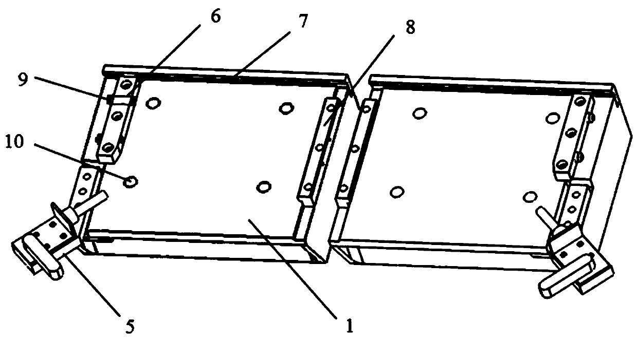
[0043] The fixing mechanism may have the following structure, which includes several installation holes 10 arranged longitudinally on the base 1, and the bolts pass through the installation holes 10 and then screwed onto the photodetector automatic crystal bonding equipment.

Embodiment 2

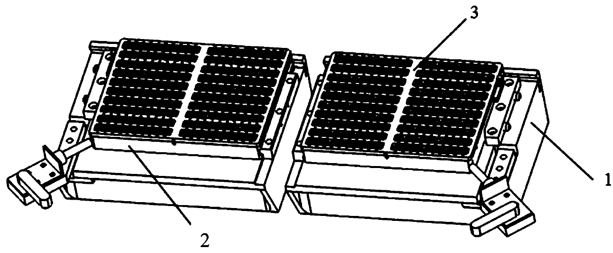
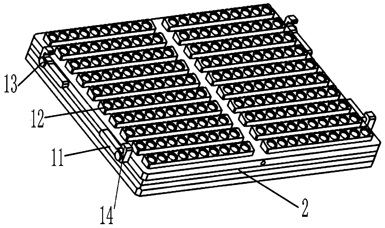
[0045] The positioning mechanism may have the following structure, which includes a stopper I 7 arranged horizontally at the rear end of the base 1, a stopper II 8 arranged vertically at the right end of the base 1, and a stopper II 8 arranged vertically at the left end of the base 1 The positioning block 6 and the toggle clamp 5 arranged at the lower left corner of the base 1 are screwed with a fixing screw 9 in the positioning block 6 . After the tube bases 22 are inserted in the tube base positioning holes 12 on each tube base mounting strip 18 in the tray 2, the tray 2 is placed on the base 1 so that the upper end of the tray 2 is aligned with the stopper I 7 contact, the left end of the tray 2 is in contact with the positioning block 6, and then by rotating the fixing screw 9, the head end of the fixing screw 9 drives the tray 2 towards the block II 8, and the tray is held by the toggle clamp 5 The lower left end of the tray 2 is locked, and finally the upper end of the t...

Embodiment 3

[0047] The cover plate fixing mechanism can be the following structure, which includes pins 19 and driving rods 11 that are horizontally arranged on the left and right sides of the cover plate 3 respectively. A hook head 14 is provided, and when the driving lever 11 is rotated to a horizontal state, the hook head 14 is hooked on the corresponding pin 19 . After the cover plate 3 is fastened to the material tray 2, move the lever 11 downward to make it rotate to a horizontal state, the hook head 14 is hooked on the pin 19 to lock and fix the cover plate 3, and the operation is simple , when unlocking, you only need to reversely turn the lever 11 to get final product.


PUM


Abstract

The invention discloses a semiconductor laser photoelectric detector die bonding clamp and a die bonding method. The semiconductor laser photoelectric detector die bonding clamp comprises a base, a positioning mechanism, a tray, tube socket positioning holes, a cover plate, elastic sheets, and a cover plate fixing mechanism. The base is fixed to a photoelectric detector die bonder, and silver colloid is smeared to the middle positions of 12-degree-angle planes of tube sockets through a dispensing head of the die bonder; and the photoelectric detector is die-bonded on the silver colloid throughsuction nozzles. The above dispensing and die bonding processes is repeated until the die bonding of the photoelectric detector is completed on the 12-degree angle planes of all the tube sockets. Finally, the positioning mechanism is loosened, and the base is taken out after die bonding. The tube sockets are reliable in fixation and convenient to replace, dispensing and die bonding work is completed on the same fixture through simple operation and automatic equipment, better conditions are provided for the next procedure, the loading capacity is greatly increased, and the production efficiency is improved.

Description

technical field [0001] The invention relates to the technical field of semiconductor laser packaging, in particular to a semiconductor laser photodetector crystal bonding fixture and a crystal bonding method. Background technique [0002] After decades of development, semiconductor lasers have become more and more well-known to the society and have been applied in many fields. The photoelectric conversion efficiency of semiconductor lasers is above 60%, which is much higher than that of other similar products. The advantages of low energy consumption, less heat accumulation in the device, long life, good collimation, and long lighting distance are more and more widely used as an emerging technology in similar industries in society. The various advantages of semiconductor lasers determine that they are getting more and more attention from all walks of life. [0003] Due to the advantages of small size, light weight, high electro-optical conversion efficiency, long life and h...

Claims


Application Information

Patent Timeline
IPC IPC(8): H01S5/00H01S5/0683B05C13/02
CPCH01S5/0014H01S5/0683B05C13/02
Inventor 张广明赵克宁汤庆敏贾旭涛
Owner 潍坊华光光电子有限公司
Why Eureka
Try Eureka