wind power equipment

A technology for wind power generation equipment and generators, which is applied to planetary gear transmissions and shafts of planetary gear transmissions. It is manufactured and used in the field of wind power generation equipment transmissions. It can solve problems such as denseness and cost, and avoid position loss and simplify Maintenance and time-saving effects

Active Publication Date: 2022-04-05
MIBA SINTER AUSTRIA
View PDF6 Cites 0 Cited by
  • Summary
  • Abstract
  • Description
  • Claims
  • Application Information

AI Technical Summary

Problems solved by technology

Replacing such plain bearings in the event of maintenance or wear is complex and therefore cost-intensive

Method used


Image

  • wind power equipment
  • wind power equipment
  • wind power equipment

Examples


Embodiment Construction

[0023] At the outset, it should be pointed out that the same reference numerals or the same component designations are used for the same components in different embodiments, wherein the disclosure content contained in the entire description can be referred to the components with the same reference numerals or the same component designations. Likewise, selected positions in the description such as above, below, side, etc. relate to the direct description and to the illustrated figures and, if the position is changed, are automatically transferred to the new position.

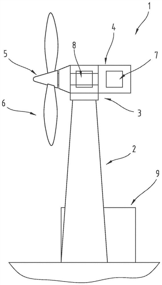
[0024] figure 1 A wind power plant 1 is shown. The wind power plant 1 corresponds in principle to the prior art, that is to say it comprises a tower 2 on which a nacelle 4 is arranged with a wind direction tracking device 3 connected in between, at the front of the nacelle a rotor with rotor blades 6 is arranged 5 and is provided with generator 7 at its rear end. Between the rotor 5 and the generator 7 , ie the...


PUM

PropertyMeasurementUnit
particle sizeaaaaaaaaaa

Abstract

The invention relates to a transmission (8) for a wind power plant comprising at least one gear (12) supported on a shaft (15), for which purpose a sliding layer (20), said sliding layer (20) is sprayed directly onto the shaft (15) by means of a thermal spraying method, or sprayed onto said further layer (21) with at least one further layer (21) in between ), the additional layer (21) is sprayed onto the shaft (15) by a thermal spraying method, and the sliding layer (20) is made of a sprayed material selected from the group consisting of aluminum-based alloys, bismuth base alloy, silver-based alloy, copper-based alloy, on the shaft (15) spray two sliding layers (20) that are spaced apart from each other in the axial direction by thermal spraying method, so that between the two sliding layers An interspace (23) is formed which is connected to the surrounding atmosphere via a connecting line which runs in the shaft (15).

Description

technical field [0001] The invention relates to a wind power plant transmission, in particular a planetary gear transmission, comprising at least one gear wheel mounted on a shaft, for which purpose a sliding layer is provided between the gear wheel and the shaft. [0002] Furthermore, the invention relates to a wind power plant with a rotor and a generator, wherein a wind power plant transmission, in particular a planetary gear, is arranged between the rotor and the generator, the wind power plant transmission being connected to the rotor and the generator Generator function connection. [0003] Furthermore, the invention relates to a method for producing a shaft for a wind power plant transmission, in particular a planetary gear transmission. Background technique [0004] It is known, for example, from DE 10260132 A1 that a planetary gear of a wind power plant for generating electricity is used to convert a relatively low rotational speed of a wind power plant rotor into ...

Claims


Application Information

Patent Timeline
Patent Type & Authority Patents(China)
IPC IPC(8): F03D15/00F16C33/14F16C33/12F16C17/02F16H57/08
CPCC23C4/067F03D80/70F16C33/14F16C2223/42F16H2057/085H05K7/18H05K7/20454H05K7/20854H05K2201/10393H05K2203/0173F16C2361/61F16C17/02F16C2360/31C23C4/06C23C28/321C23C28/324C23C28/34F05B2240/50F05B2260/40311F03D15/00F16C17/10F16C25/02Y02E10/72Y02P70/50C23C4/129F16H57/082
Inventor G·哈格尔J·S·赫茨尔
Owner MIBA SINTER AUSTRIA
Why Eureka
Try Eureka