Pipeline welding heating device as well as welding device and method

A heating device and welding device technology, applied in welding equipment, welding accessories, arc welding equipment and other directions, can solve the problems of increasing defects, failing to meet the requirements of regulations and specifications, and unable to heat the welding parts, so as to ensure the welding quality and guarantee Preheat temperature, ensure the effect of temperature requirements

Pending Publication Date: 2020-01-14
POWERCHINA SEPCO1 ELECTRIC POWER CONSTR CO LTD
View PDF11 Cites 5 Cited by
  • Summary
  • Abstract
  • Description
  • Claims
  • Application Information

AI Technical Summary

Problems solved by technology

[0002] During the automatic welding process of the pressurized pipeline in the power station, the pipeline rotates with the machine tool. For the pipeline that needs to be preheated by electric heating before welding, the equipment and tools used in the traditional electric heating preheating method cannot follow the rotation of the pipeline. It is impossible to continue electric heating preheating, so the only alternative is to use flame preheating or electric heating preheating before welding (preheating to reach the temperature first, then heating the power line and temperature measuring line when welding starts, etc. The rotating facilities are all removed), relying on the arc temperature to maintain the required preheating temperature of the pipeline itself during welding
[0003] The inventor found that the existing technology cannot continue to heat the workpiece to be welded, cannot accurately control the preheating temperature, and cannot meet the requirements of the regulations, especially for some materials that are sensitive to the preheating temperature, which greatly increases the probability of defects

Method used


Image

  • Pipeline welding heating device as well as welding device and method
  • Pipeline welding heating device as well as welding device and method
  • Pipeline welding heating device as well as welding device and method

Examples


Embodiment 2

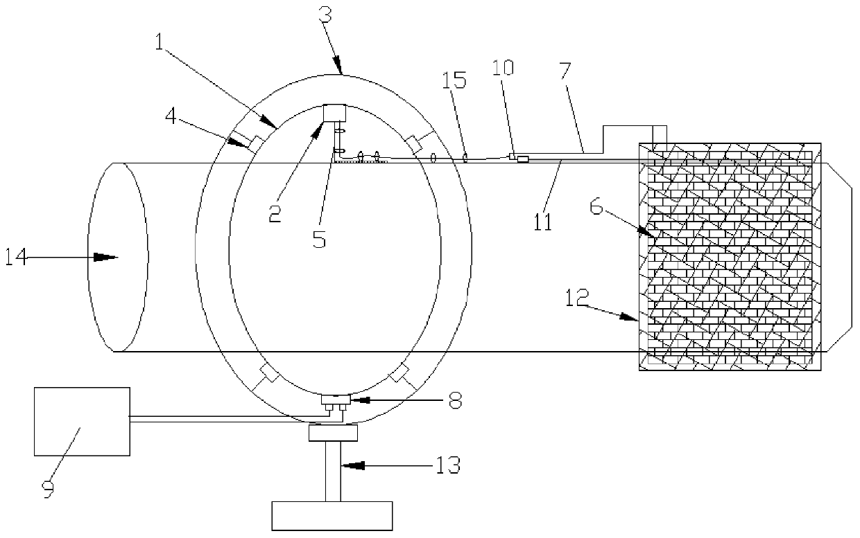
[0051] This embodiment discloses a pipe welding device, which includes a pipe automatic welding machine and two sets of pipe welding heating devices described in Embodiment 1. The sliding contact wires and brackets of the two sets of pipe welding heating devices are respectively arranged on the pipes to be welded. At both ends of the first and last ends, the sliding contact line, the bracket and the pipeline to be welded are arranged coaxially. When in use, the first and last ends of the pipeline pass through the sliding contact line.

Embodiment 3

[0053] This embodiment discloses a working method of a pipeline welding device: Figure 5 As shown, the pipeline 14 is placed on the automatic welding machine, and the pipeline welding heating device is placed on the pipeline automatic welding machine. Pass through the sliding contact line, select a suitable connecting plate to connect with the current collector, attach the connecting plate to the pipeline to be welded by magnets, fix the thermocouple on the pipeline to be welded by binding iron wire, and the distance between the thermocouple and the groove at the end of the pipeline is 20mm -30mm, then wrap the resistance ceramic heater on the outer peripheral surface of the end of the pipe, and the thermocouple extends between the resistance ceramic heater and the pipe, that is, the thermocouple extends into the heating area of ​​the resistance ceramic heater, and the resistance ceramic heater After installation, wrap the thermal insulation blanket around the outer periphery...


PUM

PropertyMeasurementUnit
lengthaaaaaaaaaa

Abstract

The invention relates to a pipeline welding heating device as well as a welding device and method. The heating device comprises a circular sliding contact line; the sliding contact line and a to-be-welded pipeline are arranged coaxially; the to-be-welded pipeline can penetrate through the sliding contact line; the sliding contact line is fixedly connected with a support; the support is used for fixing the sliding contact line; the sliding contact line is connected with a current collector; the current collector can slide along the sliding contact line; the current collector is fixedly connected with a connecting plate; the connecting plate is fixedly connected with the to-be-welded pipeline; the to-be-welded pipeline can rotate to drive the current collector through the connecting plate tomove along the sliding contact line; the current collector is connected with a heater through a heat treatment wire; the heater is fixed to the to-be-welded pipeline and is used for heating the to-be-welded pipeline; a connector is arranged at a joint of a sliding contact device; and the connector is connected with a heat treatment machine. By the aid of the heating device, continuous heating canbe performed during pipeline welding, so that the welding quality is high.

Description

technical field [0001] The invention relates to the technical field of welding equipment, in particular to a pipe welding heating device, a welding device and a method. Background technique [0002] During the automatic welding process of the pressurized pipeline in the power station, the pipeline rotates with the machine tool. For the pipeline that needs to be preheated by electric heating before welding, the equipment and tools used in the traditional electric heating preheating method cannot follow the rotation of the pipeline. It is impossible to continue electric heating preheating, so the only alternative is to use flame preheating or electric heating preheating before welding (preheating to reach the temperature first, then heating the power line and temperature measuring line when welding starts, etc. The rotating facilities are all removed), relying on the arc temperature to maintain the required preheating temperature of the pipeline itself during welding. [0003...

Claims


Application Information

Patent Timeline
Patent Type & Authority Applications(China)
IPC IPC(8): B23K9/32B23K9/18
CPCB23K9/32B23K9/18
Inventor 李保吴富强王小龙彭晶李振
Owner POWERCHINA SEPCO1 ELECTRIC POWER CONSTR CO LTD
Why Eureka
Try Eureka