
Clamp for pipeline clamping

A pipe and fixture technology, applied in the field of pipe clamping equipment, achieves the effect of accurate and stable three-point positioning and stable clamping force

Pending Publication Date: 2020-01-14
无锡市迪索数控焊接设备有限公司
View PDF0 Cites 2 Cited by
  • Summary
  • Abstract
  • Description
  • Claims
  • Application Information

AI Technical Summary

Problems solved by technology

[0004] Purpose of the invention: The purpose of the invention is to provide a clamp for pipe clamping, which solves the problem of pipe positioning and locking

Method used


Image

  • Clamp for pipeline clamping
  • Clamp for pipeline clamping

Examples


Embodiment Construction

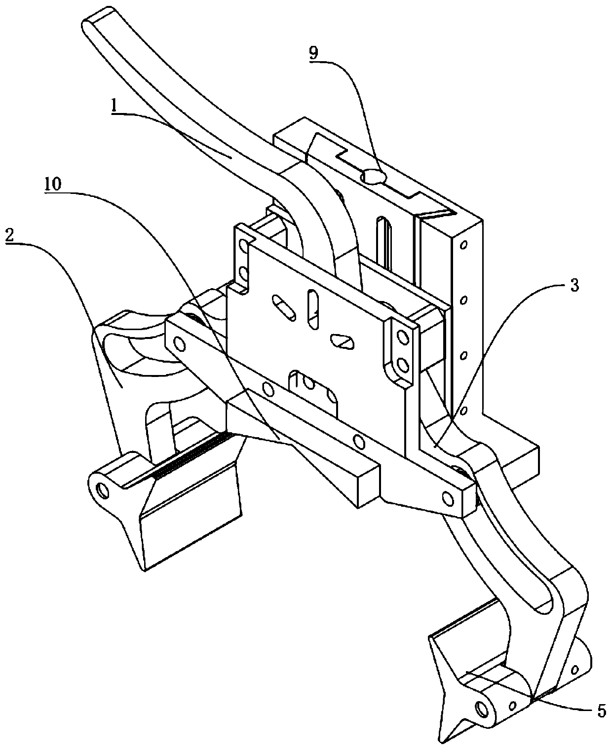
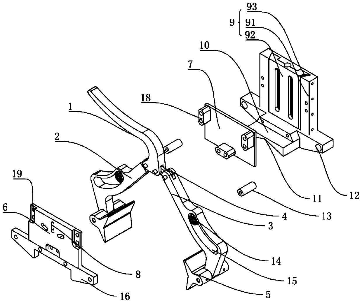
[0017] Such as figure 1 and 2 As shown, a clamp for pipe clamping includes a clamping handle 1, clamping rod one 2 and clamping rod two 3, a pair of clamping jaws 5, a front wall 6 and a rear wall 7, a lifting assembly 9 and a stopper Block 10.

[0018] The clamping handle 1 is used to radially lock or release the pipeline, and the bottom end of the clamping handle 1 is provided with a transverse block with grooves 19 at both ends.

[0019] Clamping rod one 2 and clamping rod two 3, clamping rod one 2 is embedded in the groove 19 of the horizontal line block of clamping handle 1, and is hinged with clamping handle 1, clamping rod two 3 is hinged with transition piece 4, transition piece 4 Embedded in the groove 19 at one end of the transverse block of the clamping handle 1, and hinged with the clamping handle 1, pin shafts are installed at each of the above-mentioned hinges and a certain length is reserved for the pin shafts, and the reserved length of the pin shafts is used...


PUM


Abstract

The invention discloses a clamp for pipeline clamping. According to the clamp for pipeline clamping, through the movement of double clamping jaws to lock a pipeline, the pipeline can be prevented frombeing offset in the clamping process; and the whole clamping process of the clamp is an arc movement mode, compared with a linear movement mode by which the pipeline is locked the pipeline, the clamping force of the arc movement mode is stabler. According to the clamp for pipeline clamping, three-point positioning and circle center alignment are achieved through an inverted-V-shaped stop block, and compared with existing two-point positioning, three-point positioning is more accurate and stabler.

Description

technical field [0001] The invention relates to pipeline clamping equipment, in particular to a clamp for pipeline clamping. Background technique [0002] Welding is a manufacturing process and technology that uses heat, high temperature or high pressure to join metal or other thermoplastic materials such as plastics. There are many sources of energy for modern welding, including gas flames, electric arcs, lasers, electron beams, friction, and ultrasound. [0003] Pipes are widely used, mainly in water supply, drainage, heat supply, gas supply, long-distance transportation of oil and natural gas, agricultural irrigation, hydraulic engineering and various industrial devices. One of the most common techniques for pipe installation when welding straight pipes. In order to extend the length of the pipe; when the pipe is welded, it is necessary to align the two ends of the welded pipe. However, the outer wall of the pipe is smooth and difficult to fix. Ensure that the butt join...

Claims


Application Information

Patent Timeline
IPC IPC(8): B23K37/053B29C65/00
CPCB23K37/053B29C65/00
Inventor 俞琳俞谷峰
Owner 无锡市迪索数控焊接设备有限公司
Learn More