Automatic feeding and discharging robot unit for automatic machining equipment and method

A technology for automatic loading and unloading and processing equipment, applied in the field of robots, can solve the problems of limiting the production capacity of production equipment, high labor intensity of operators, and high error rate of manual loading and unloading, achieving automatic operation, saving manpower and material resources, and ensuring universality Effect

Active Publication Date: 2020-01-14
SHANGHAI UNIV
View PDF12 Cites 14 Cited by
  • Summary
  • Abstract
  • Description
  • Claims
  • Application Information

AI Technical Summary

Problems solved by technology

[0004] The purpose of the present invention is to solve the problem of using manual loading and unloading operations in the loading and unloading process of existing automatic processing equipment, which requires a large number of operators, and the labor intensity of the operators is too high. The production capacity of the production equipment is limited, the error rate of manual loading and unloading is high, the rate of defective products is high, the product control is difficult, the production efficiency is low, and the labor cost is high. An automatic loading and unloading robot for automatic processing equipment is proposed. Units and Methods

Method used


Image

  • Automatic feeding and discharging robot unit for automatic machining equipment and method
  • Automatic feeding and discharging robot unit for automatic machining equipment and method
  • Automatic feeding and discharging robot unit for automatic machining equipment and method

Examples


Embodiment 1

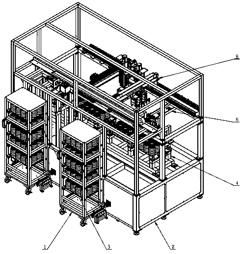
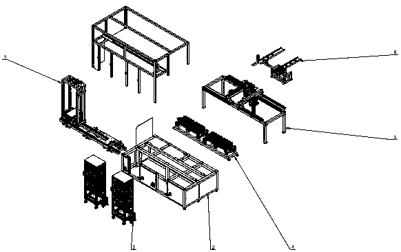
[0041] see Figure 1-10 , the automatic loading and unloading robot unit used for automatic processing equipment, including equipment frame 2, material trolley 1, pallet servo component 3, station pallet raceway 4, dual three-axis robot component 5, loading and unloading conveyor belt 6 and the general control device7.

[0042] It is characterized in that there are two cargo trolleys, which are side by side and detachably fastened on the front side of the equipment frame 2; the tray servo assembly 3 is installed in the front lower part of the equipment frame 2; the station tray raceway 4 is installed in the middle of the equipment frame 2; the double-three-axis robot assembly 5 is installed in the rear upper part of the equipment frame 2; the loading and unloading conveyor belt 6 is fixedly connected to the rear side of the equipment frame 2; Connect and control the material trolley 1, the pallet servo component 3, the station pallet raceway 4, the dual-three-axis robot compo...

Embodiment 2

[0045] see Figure 1-10 , an automatic loading and unloading robot unit for automatic processing equipment, including a material trolley 1, an equipment frame 2, a pallet servo assembly 3, a station pallet raceway 4, a double-three-axis robot assembly 5, and a loading and unloading conveyor belt 6.

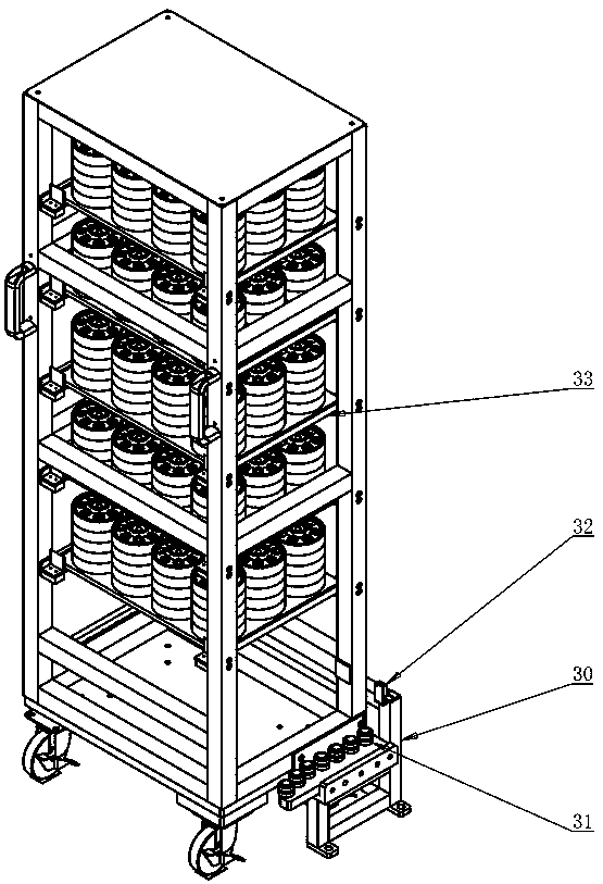
[0046] It is characterized in that the cargo trolley 1 is placed at the front of the equipment, and is used to hold cargo pallets and transport OEM products. A wheel centering mechanism 30 is arranged under the cargo trolley 1, and the wheel The centering mechanism 30 is connected to the equipment frame 2, the front bottom beam of the equipment frame 2 is connected to the pallet servo assembly 3, the bottom of the station pallet raceway 4 is connected to the bottom beam of the equipment frame 2, and the double The bottom of the three-axis robot assembly 5 is connected to the rear column of the equipment frame 2, and the loading and unloading conveyor belt 6 is connected to the rea...


PUM


Abstract

The invention relates to an automatic feeding and discharging robot unit for automatic machining equipment and method. The equipment comprises a equipment frame, cargo material trolleys, a tray servoassembly, a station tray rollway, a double-triaxial robot assembly, a feeding and discharging conveyor belt and a total controller, wherein the two cargo material trolleys are provided and connected to the front side of the equipment frame in a buckled, left-and-right side by side mode, the tray servo assembly is mounted in the front lower portion of the equipment frame, the station tray rollway is mounted in the middle of the equipment frame, the double-triaxial robot assembly is mounted in the rear upper portion of the equipment frame, the feeding and discharging conveyor belt is fixedly connected to the rear side of the equipment frame, and the total controller is electrically connected with and controls the tray servo assembly, the station tray rollway, the double-triaxial robot assembly and the feeding and discharging conveyor belt; a machining material is placed in a material tray, and is conveyed to the front of the equipment frame from the cargo material trolley on the left side, and after the cargo material trolleys are connected with the equipment frame in a buckled mode, the tray servo assembly brings and conveys the material to the feeding and discharging conveyor beltby the double-triaxial robot assembly through tray rollways; and machined finished products are reversely conveyed to the cargo material trolley on the right to complete feeding and discharging. According to the automatic feeding and discharging robot unit and the method, full automation of workshop production can be realized, and the production efficiency is improved.

Description

technical field [0001] The invention relates to a robot, in particular to an automatic loading and unloading robot unit and method for automatic processing equipment, belonging to the technical field of automatic loading and unloading robots. Background technique [0002] With the continuous improvement of people's living standards and the development and improvement of robot technology, robots are used more and more frequently in parts processing. The loading and unloading robot is mainly used to move and load the materials required for part processing before part processing, and after part processing, to grasp and move the processed parts to improve the processing efficiency of parts. [0003] At present, in the production process of most enterprises, the loading and unloading process of automated processing equipment still uses manual use of driving or forklift trucks to transport materials. This method requires operators to manually perform loading and unloading operatio...

Claims


Application Information

Patent Timeline
Patent Type & Authority Applications(China)
IPC IPC(8): B65G47/06B65G47/90B65G43/00
CPCB65G43/00B65G47/06B65G47/901
Inventor 何永义温可侯涛
Owner SHANGHAI UNIV
Why Eureka
Try Eureka