Differential circuit protection method

A circuit and protection device technology, applied in the protection field of differential circuits, can solve problems such as poor reliability of differential protection action, and achieve the effects of low cost, simple implementation process, and elimination of unbalanced differential current.

Active Publication Date: 2020-01-14
河南许继继保电气自动化有限公司 +3
View PDF1 Cites 4 Cited by
  • Summary
  • Abstract
  • Description
  • Claims
  • Application Information

AI Technical Summary

Problems solved by technology

[0004] The purpose of the present invention is to provide a protection method for a differential circuit to solve the problem of poor reliability of the differential protection operation caused by the influence of power frequency interference on the differential circuit

Method used


Image

  • Differential circuit protection method
  • Differential circuit protection method

Examples


Embodiment 1

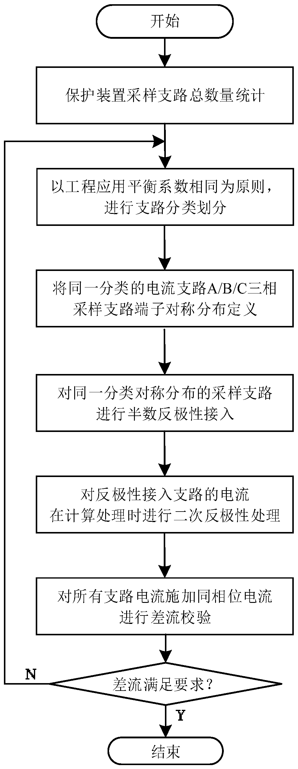
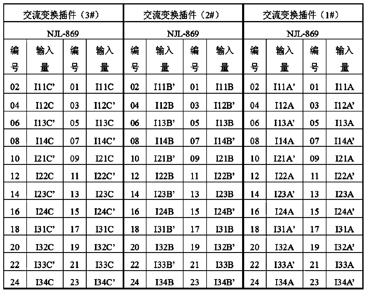
[0018] For the sampling branch connected to the differential circuit of the protection device through the AC conversion plug-in (referred to as the plug-in), taking 12 sampling branches as an example, the method for eliminating power frequency interference of the differential circuit is introduced, as follows: figure 1 As shown, the AC conversion plug-in is an AC conversion small transformer plug-in, and the differential circuit collected by the protection device is the three-phase current of the secondary circuit of the AC conversion small transformer.

[0019] Step 1: Count the total number N of each sampling branch connected to the differential circuit of the protection device, and the total number N=12.

[0020] Step 2, based on the principle that the current balance coefficients of the sampling branches are the same, then a total of N sampling branches are classified and marked as Lij, where i represents the number of current balance coefficients (i=1, 2...N) , j represen...

Embodiment 2

[0044] The difference between this embodiment and method embodiment 1 lies in that: in step 4, the reverse access method is different.

[0045] The specific reverse connection method is to reverse the positive and negative polarities of the access terminals of the sampling branch L11 and the sampling branch L13 in the first category on the plug-in of the AC conversion small transformer of the protection device, and reverse the positive and negative polarities of the sampling branch L13 in the second category. The positive and negative polarities of the access terminals of the branch L21 and the sampling branch L23 on the plug-in of the small transformer of the protection device are reversed, and the sampling branch L31 and the sampling branch L33 in the third category are connected to the plug-in of the small transformer of the protection device. The positive and negative polarities of the access terminals on the transformer plug-in are reversed.

[0046] As other implementati...


PUM


Abstract

The invention relates to a differential circuit protection method, and the method comprises the following steps: (1) setting N sampling branches in a differential circuit, wherein each sampling current branch is connected to a protection device through a plug connector, and the positive and negative polarities of the plug connectors of the M sampling branches are oppositely inverted to be connected into the protection device, and N >M>= 1; (2) during the calculation of the unbalanced current values of the N sampling branches, performing phase inversion processing on the currents of the M sampling branches, and adding the currents of the M sampling branches and the currents of the other N-M sampling branches to serve as actual unbalanced currents of the N sampling branches; (3) performing differential protection action according to the unbalanced current. On the basis of not changing the hardware loop of the original protection device, the unbalanced differential current caused by powerfrequency interference can be eliminated only by adjusting the wiring mode of part of terminals of the sampling branch, so that the reliability of differential protection is improved.

Description

technical field [0001] The invention relates to a protection method for a differential circuit. Background technique [0002] High-voltage, large-capacity, and long-distance power transmission and transformation equipment are continuously put into power grid operation, which makes the power frequency magnetic field interference in substations more and more serious. The secondary circuit of high-voltage substation protection devices often uses cables, so the protection device itself needs to be equipped with AC conversion small transformers to complete the small signal data required for AD sampling, which will be introduced on the secondary side of the AC conversion small transformers. Power frequency interference. [0003] With the expansion of the grid scale, the number of current branches connected to differential protection devices is gradually increasing, such as busbar differential protection, transformer differential protection, etc., sometimes it is necessary to conn...

Claims


Application Information

Patent Timeline
IPC IPC(8): H02H7/22H02H7/045H02H3/26H02H1/00
CPCH02H7/22H02H7/045H02H3/26H02H1/0038
Inventor 陈继瑞李宝伟李旭邓茂军马和科王东兴张哲杨振良原琳吕利娟张真苏亚昕闫志辉陈晨于士谦
Owner 河南许继继保电气自动化有限公司
Why Eureka
Try Eureka