Electronic element mounting base convenient for heat dissipation

A technology of electronic components and mounting bases, which is applied in the direction of electrical components, electrical solid devices, electrical equipment structural parts, etc., can solve the problem of inflexible adjustment of mounting bases for electronic components, increase the workload of operators, and increase the economic value of enterprises Expenditure and other issues, to achieve the effect of improving heat dissipation, improving the stability of use, and facilitating replacement

Inactive Publication Date: 2020-01-14
徐州力驰智能科技有限公司
View PDF0 Cites 2 Cited by
  • Summary
  • Abstract
  • Description
  • Claims
  • Application Information

AI Technical Summary

Problems solved by technology

[0006] The purpose of the present invention is to provide a mounting seat for electronic components that is convenient for heat dissipation, so as to solve the problem that the existing mounting base for electronic components in the above-mentioned background technology cannot flexibly install the electronic components due to its insufficient heat dissipation function when in use. For heat dissipation treatment, special heat dissipation tools are required to assist, which increases the economic expenditure of the enterprise, and the existing electronic component mounts cannot be adjusted flexibly, so that the operator is comfortable when working, and thus increases the operating cost. staff workload

Method used


Image

  • Electronic element mounting base convenient for heat dissipation
  • Electronic element mounting base convenient for heat dissipation
  • Electronic element mounting base convenient for heat dissipation

Examples


Embodiment Construction

[0024] The following will clearly and completely describe the technical solutions in the embodiments of the present invention with reference to the drawings in the embodiments of the present invention.

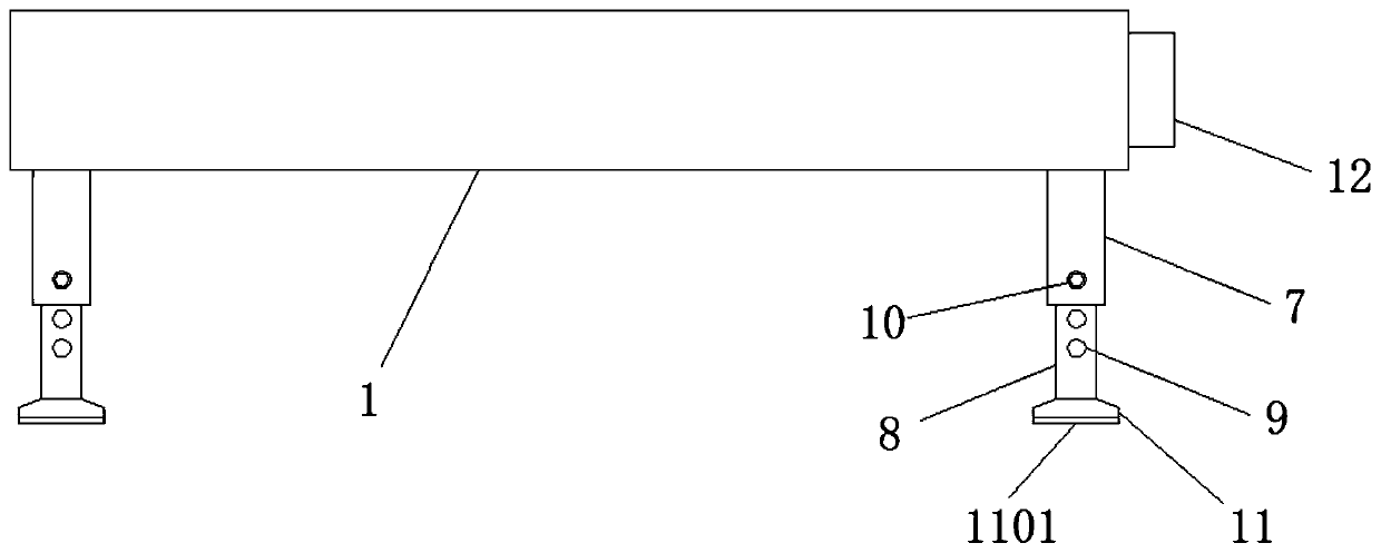
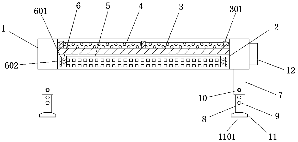
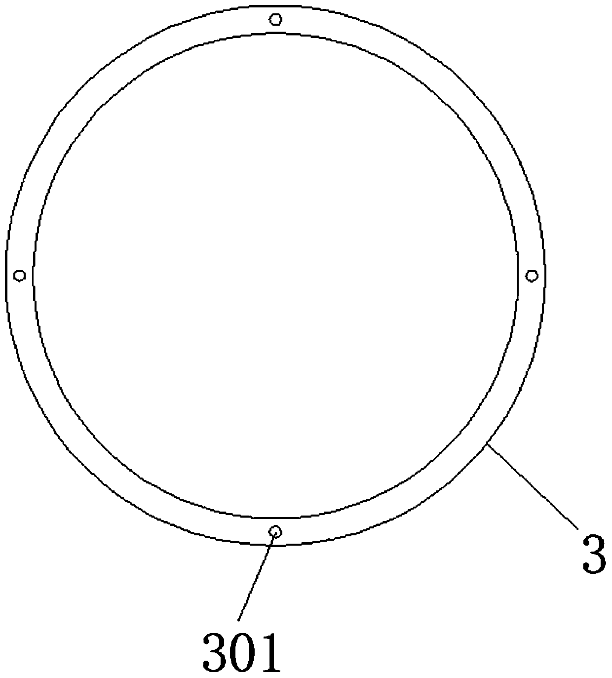
[0025] Such as Figure 1-6 As shown, a mounting seat for electronic components that is convenient for heat dissipation includes a mounting seat main body 1, a through hole 2 is opened on the top surface of the mounting seat main body 1, and the through hole 2 runs through the mounting seat main body 1, and the inside of the through hole 2 A retaining ring 3 is installed on the surface of the side wall of the cavity, and the top surface of the retaining ring 3 is provided with a limit post 301, and a hollow plate 4 is installed on the top surface of the limit post 301, and a limit groove 401 is provided on the surface of the hollow plate 4, so that A fixed frame 5 is installed on one side of the bottom of the retaining ring 3, and a heat dissipation fan 501 is installed in the ...


PUM


Abstract

The invention discloses an electronic component mounting base convenient for heat dissipation. The mounting base comprises a mounting base main body, and a through hole is formed in the surface of thetop of the mounting base main body, and penetrates through the mounting base main body; a check ring is mounted on the surface of the side wall of an inner cavity of the through hole; a limiting column is arranged on the surface of the top of the check ring; a hollowed-out plate is mounted on the surface of the top of the limiting column; a limiting groove is formed in the surface of the hollow plate; a fixed frame is mounted on one side of the bottom of the check ring; and cooling fans are mounted in an inner cavity of the fixed frame. According to the invention, a plurality of groups of cooling fans are arranged in the fixed frame; the bottom of the hollow plate can be cooled; holes are formed in the surface of the hollow plate; and meanwhile, the damping springs can reduce the influence of vibration generated during operation of the cooling fans on the mounting base main body, the depth of the supporting legs inserted into the sleeves can be flexibly adjusted through the screw holes and the bolts, and therefore, an operator can flexibly adjust and use the mounting base conveniently according to his/her own needs.

Description

technical field [0001] The invention relates to the technical field of mounting seat equipment, in particular to a mounting seat for electronic components that facilitates heat dissipation. Background technique [0002] Electronic components are basic elements in electronic circuits, usually individually packaged, and have two or more leads or metal contacts. Electronic components must be connected to each other to form an electronic circuit with specific functions, such as amplifiers, radio receivers, oscillators, etc. One of the common ways to connect electronic components is to solder them to a printed circuit board. Electronic components may be individual packages (resistors, capacitors, inductors, transistors, diodes, etc.), or groups of varying complexity, such as integrated circuits (op amps, resistors, logic gates, etc.). [0003] However, there are following disadvantages in existing mounts for electronic components: [0004] 1. When the existing mounting base for...

Claims


Application Information

Patent Timeline
Patent Type & Authority Applications(China)
IPC IPC(8): H05K7/20F16M11/26F16M11/36H01L23/32
CPCF16M11/26F16M11/36H01L23/32H05K7/20136H05K7/20145H05K7/20172
Inventor 王亮黄继战范玉张厚东
Owner 徐州力驰智能科技有限公司
Why Eureka
Try Eureka