Economical irrigation device for agricultural greenhouses

An irrigation device, an economical technology, applied in agriculture, a device for capturing or killing insects, a mixer with a rotary stirring device, etc. Market promotion prospects, efficiency improvement, and the effect of expanding the irrigated area

Inactive Publication Date: 2020-01-17
林章进
View PDF10 Cites 5 Cited by
  • Summary
  • Abstract
  • Description
  • Claims
  • Application Information

AI Technical Summary

Problems solved by technology

[0004] The purpose of the present invention is to solve the problem that the interior of the greenhouse in the prior art is convenient for irrigation, so there are multiple irrigation systems inside, but the existing greenhouse irrigation system consumes a lot of water, and at the same time, it is impossible to put chemicals into the irrigation system Spraying in the middle, so the existing irrigation system has many inconvenient shortcomings, and a saving-type agricultural greenhouse irrigation device is proposed

Method used


Image

  • Economical irrigation device for agricultural greenhouses
  • Economical irrigation device for agricultural greenhouses
  • Economical irrigation device for agricultural greenhouses

Examples


Embodiment 1

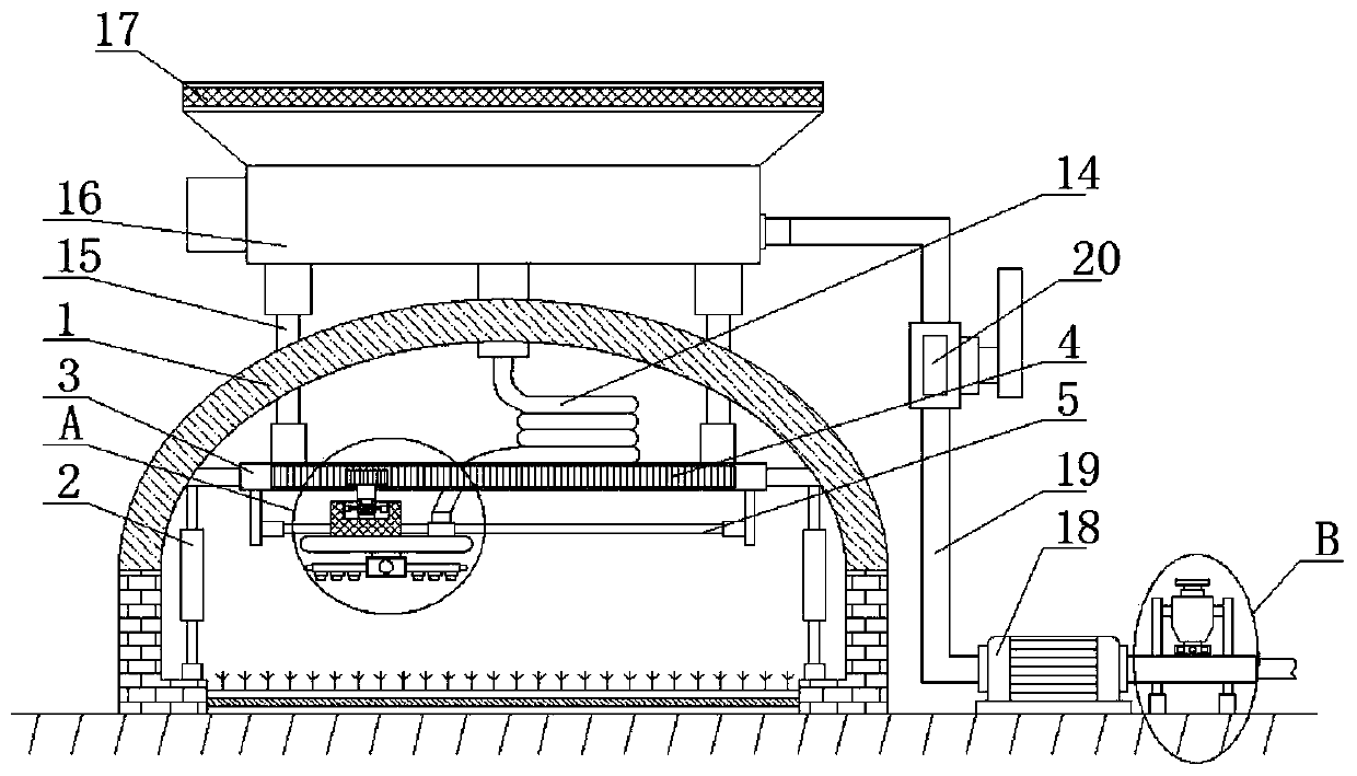
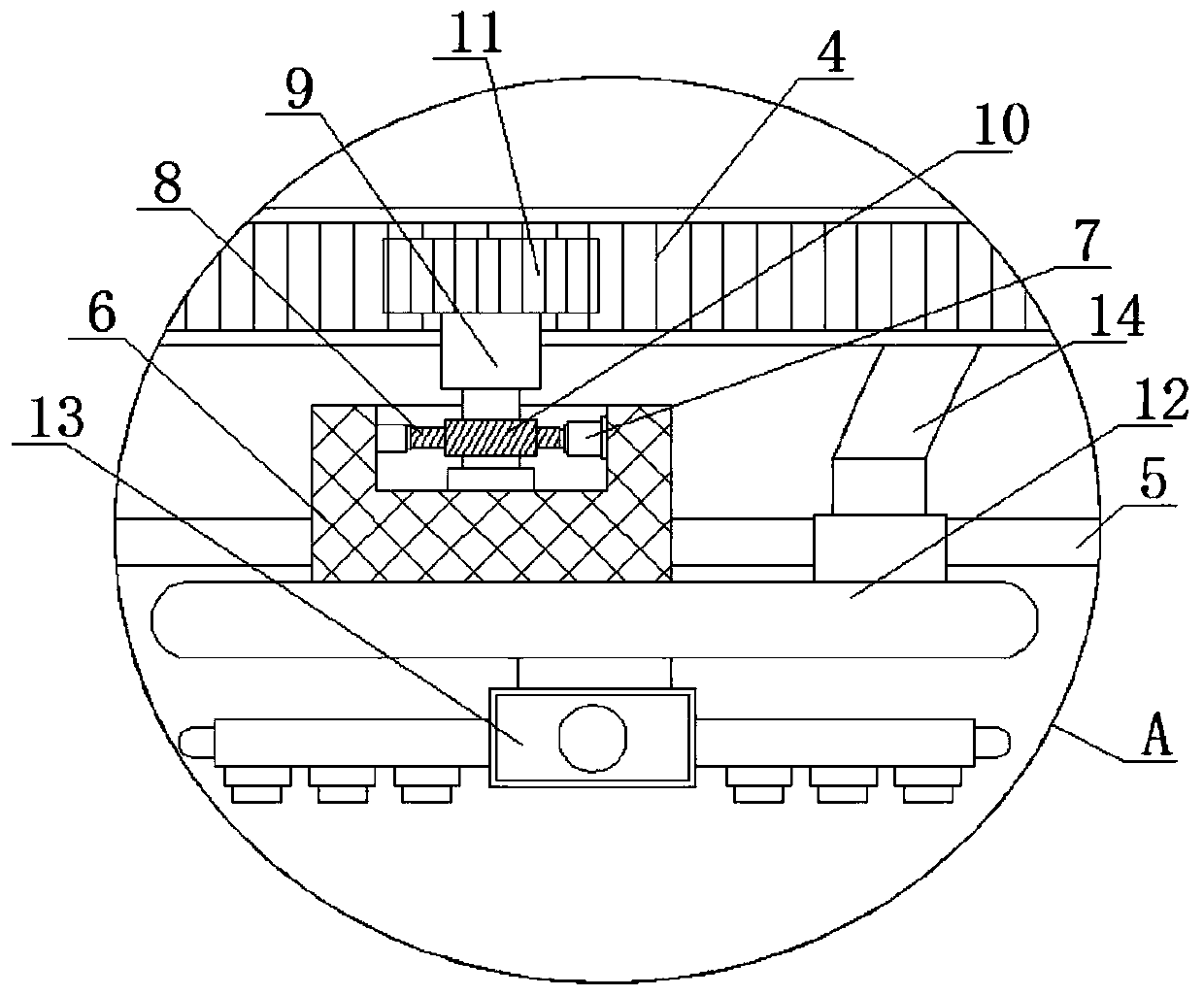
[0028] refer to Figure 1-5 , an energy-saving agricultural greenhouse watering device, including two support frames 2 fixedly installed in the greenhouse 1, the tops of the two support frames 2 are fixedly connected with the same fixed plate 3, and the bottom of the fixed plate 3 is slidably connected with a mobile seat 6. The moving base 6 is fixedly connected with a drive assembly, the bottom of the moving base 6 is fixedly connected with a water pipe 12, the bottom of the water pipe 12 is fixedly connected with a rotating nozzle 13, and the bottom of the fixed plate 3 is fixedly connected with a slide bar 5, and the slide bar 5 runs through the moving seat 6 and is slidably connected with the moving seat 6, and the top of the fixed plate 3 is fixedly connected with two vertical bars 15 arranged symmetrically, and the tops of the two vertical bars 15 all extend to the top of the greenhouse 1 and are fixedly connected with the same A mixing box 16, the bottom of the mixing b...

Embodiment 2

[0030]The driving assembly includes a turning groove provided at the top of the moving seat 6, and the bottom inner wall of the turning groove is rotatably connected with a rotating shaft 9; Into the motor 7, the output shaft of the stepper motor 7 is fixedly connected with a worm 8, and the worm 8 is meshed with the worm wheel 10, the top of the rotating shaft 9 extends to one side of the fixed plate 3, and the top of the rotating shaft 9 is fixedly connected with a gear 11. One side of the fixed plate 3 is fixedly connected with the rack 4, and the gear 11 and the rack 4 are meshed. When it is necessary to drive the rotating nozzle 13 to move laterally, the stepper motor 7 is started at this time, and the worm gear 10 and Under the cooperation of the worm screw 8, the rotating shaft 9 can be driven to rotate, and the gear 11 on the rotating shaft 9 is meshed with the rack 4 on the fixed plate 3, so the rotating nozzle 13 can be driven to move laterally and spray, thereby expa...


PUM


Abstract

The invention belongs to the technical field of greenhouse irrigation, and particularly relates to an economical irrigation device for agricultural greenhouses. Aiming at solving the problem that theexisting greenhouse irrigation system is high in water consumption, with a pesticide unsuitable for being put into the irrigation system to be sprayed at the same time, so that many inconveniences arecaused to the irrigation system, the following scheme is provided. The economical irrigation device for agricultural greenhouses comprises two supports fixedly mounted in a greenhouse; the tops of the two supports are fixedly connected with a same fixing plate; a movable seat is slidably connected to the bottom of the fixing plate, and a driving assembly is fixedly connected onto the movable seat; the bottom of the movable seat is fixedly connected with a water pipe; The economical irrigation device for agricultural greenhouses is simple to operate; on one hand, rainwater can be collected fordaily irrigation of the greenhouse; on the other hand, a pesticide can be added in the irrigation process to arrive at weeding and insect elimination; therefore, the efficiency of the planting greenhouse is effectively improved, and the economical irrigation device for agricultural greenhouses has a good market popularization prospect.

Description

technical field [0001] The invention relates to the technical field of greenhouse irrigation, in particular to an energy-saving irrigation device for agricultural greenhouses. Background technique [0002] Greenhouses are also called greenhouses. A facility that can transmit light, keep warm (or warm), and be used to grow plants. In seasons that are not suitable for plant growth, it can provide a greenhouse growth period and increase production. It is mostly used for planting or raising seedlings of temperature-loving vegetables, flowers, forest trees and other plants in low temperature seasons. There are many types of greenhouses, which can be divided into many types according to different roof truss materials, lighting materials, shapes and heating conditions. The design of the greenhouse system includes heating systems, heat preservation systems, cooling systems, ventilation systems, control systems, irrigation System, etc.; the greenhouse is just a simple plastic film ...

Claims


Application Information

Patent Timeline
IPC IPC(8): A01G9/24A01M7/00B01F7/04
CPCA01G9/247A01M7/0014A01M7/005A01M7/0089B01F27/191B01F27/70Y02A40/25
Inventor 不公告发明人
Owner 林章进
Why Eureka
Try Eureka