Supercharge Your Innovation With Domain-Expert AI Agents!

Auxiliary device for channel expansion of neuroendoscopic surgery

A surgical channel and auxiliary device technology, applied in the field of neuroendoscopic surgery, can solve problems affecting doctors' operations and loss of nerve tissue

Inactive Publication Date: 2020-01-17
PEKING UNION MEDICAL COLLEGE HOSPITAL CHINESE ACAD OF MEDICAL SCI
View PDF6 Cites 1 Cited by
  • Summary
  • Abstract
  • Description
  • Claims
  • Application Information

AI Technical Summary

Problems solved by technology

[0003] When people have brain lesions, doctors need to cut the cerebral cortex for treatment, and directly reach the lesion area for surgery, but there are too many nerve tissues in the brain. The tissue often accumulates and closes, which will affect the doctor's operation. It is necessary to traction and locate the nerve tissue on both sides of the cerebral cortex channel, and at the same time, the nerve tissue cannot be lost

Method used


Image

  • Auxiliary device for channel expansion of neuroendoscopic surgery
  • Auxiliary device for channel expansion of neuroendoscopic surgery
  • Auxiliary device for channel expansion of neuroendoscopic surgery

Examples


Embodiment 1

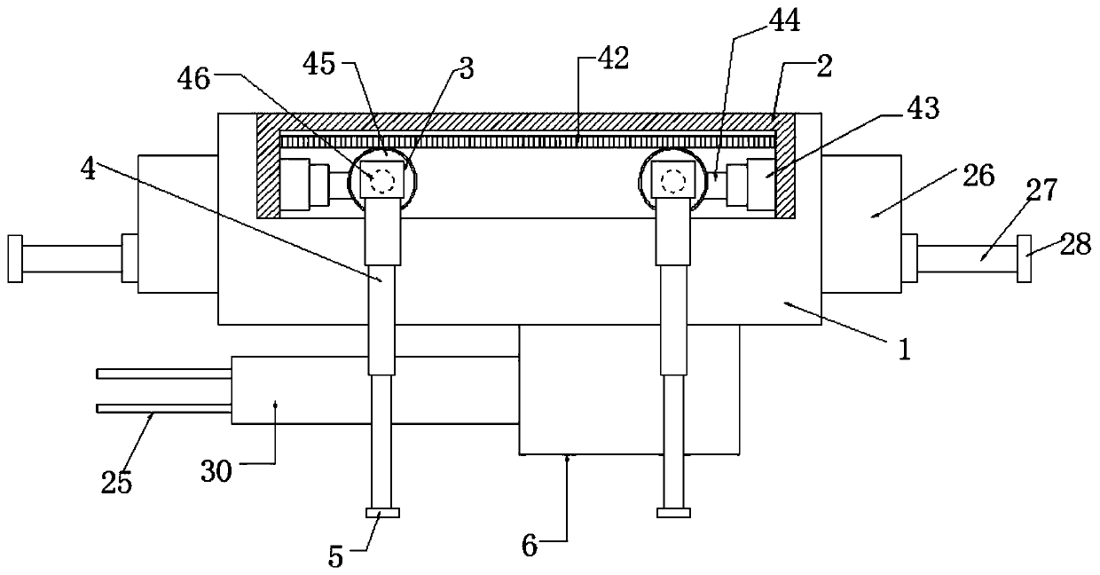
[0030] Embodiment one, such as figure 1 , 3 As shown, an auxiliary device for neuroendoscopic surgery channel expansion according to an embodiment of the present invention includes a fixed plate 1, and an inverted U-shaped plate 2 is welded on the side and top of the fixed plate 1, and the U-shaped plate 2 Both ends of the U-shaped groove of the motor are provided with three motors 3, and the output ends of the motor three 3 are connected with two telescopic rods 4, and the two telescopic rods 4 all pass through the U-shaped plate 2 and extend to the U-shaped plate 2. A vacuum suction cup 5 is provided under the template 2;

[0031] One end of the bottom of the fixed plate one 1 is welded with a fixed plate two 6, and the bottom side of the fixed plate two 6 and away from the U-shaped plate 2 is provided with a slide plate one 7, on which the slide plate one 7 is far away from the fixed plate. One side of the board one 1 is provided with a rack one 8 which is slidably matche...

Embodiment 2

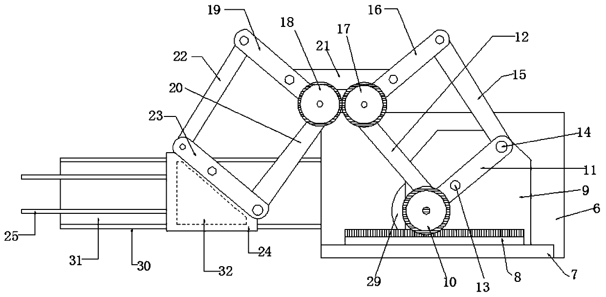
[0033] Embodiment two, such as image 3 As shown, the middle part of the gear 10 is interspersed with a rotating shaft, and the rotating shaft passes through the ends of the connecting plate 11 and the connecting plate 4 12 and the L-shaped support plate 9 extends to the L On the other side of the type support plate 9, the end of the rotating shaft and away from the gear one 10 is provided with a motor one 29, and the motor one 29 is fixed on the side end of the fixed plate two 6, and the fixed plate Two 6 and the same side of the push plate 24 are welded with a slide plate two 30, the slide plate two 30 is provided with a chute one 31 near the side of the push plate 24, wherein the push plate 24 corresponds to the slide The side of groove one 31 is provided with the slide block 32 that slides with described chute one 31, and the two ends of described fixed plate three 21 are all fixed on described connecting plate three 16 and described connecting plate five by fixing screws....

Embodiment 3

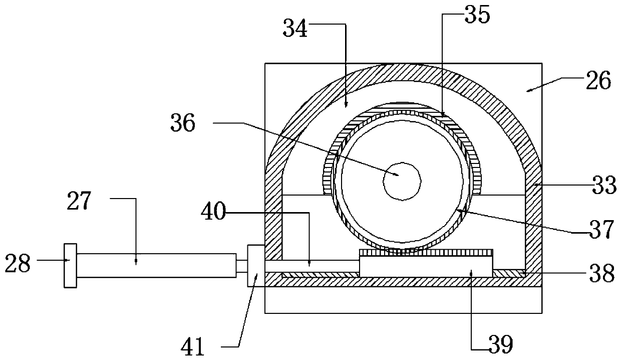
[0034] Embodiment three, such as figure 2 As shown, the side of the fixed plate 26 is welded with a frame 33, the upper part of the frame 33 is welded with a semi-arc structure 34, the inside of the semi-arc structure 34 is provided with gear teeth 35, and the semi-arc structure 34 is interspersed with a rotating shaft 36 in the lower part of the lower part. The rotating shaft 36 is provided with a full gear 37 meshed with the gear teeth 35. The inner bottom of the frame 33 is provided with a second chute 38, and the second chute 38 is A half gear 39 that is slidably matched with the chute two 38 and meshed with the full gear 37 is provided, and the end of the half gear 39 and away from the fixed plate one 1 is provided with a pole 40, and the pole 40 is arranged on the end of the half gear 39. The rod 40 penetrates through the frame 33 and extends to the outside of the frame 33, wherein a sleeve 41 is provided at the bottom of the fixed plate 26 and away from the fixed plate...


PUM


Abstract

The invention discloses an auxiliary device for channel expansion of neuroendoscopic surgery. The device comprises a fixing plate 1, the top of one side of the fixing plate 1 is welded with an inverted U-shaped plate, the two ends of a U-shaped groove of the U-shaped plate are respectively provided a motor 3, the output end of each motor 3 is connected with a telescopic rod 2, and each telescopicrod 2 penetrates through the U-shaped plate and is provided with a vacuum suction cup; and one end of the bottom of the fixing plate 1 is welded with a fixing plate 2, the bottom of one side of the fixing plate 2 far away from the U-shaped plate is provided with a sliding plate 1, one side of the sliding plate 1 far away from the fixing plate 1 is provided with a rack 1 which is slidingly matchedwith the sliding plate 1, the end of one side of the sliding plate 1 closed to the fixing plate 2 is provided with an L-shaped support plate, and the lower part of one side of the L-shaped support plate far away from the fixing plate 2 is provided with a gear 1 which is meshed with the rack 1. Traction and fixation of the cut cerebral cortex channel is performed by the auxiliary device, doctors are aided to performed surgery, and the auxiliary device facilitate neuroendoscopic surgery to carry out normally.

Description

technical field [0001] The invention relates to the technical field of neuroendoscopic surgery, in particular to an auxiliary device for channel expansion of neuroendoscopic surgery. Background technique [0002] Neuroendoscope is a tool for observation and operation in endoscopic neurosurgery. Clinically commonly used neuroendoscopes include rigid endoscopes and flexible endoscopes, and the development of the latter has gone through two stages: fiber optic endoscopes and electronic flexible endoscopes. Neuroendoscopic surgery has become one of the main development directions of modern minimally invasive neurosurgery. [0003] When people have brain lesions, doctors need to cut the cerebral cortex for treatment, and directly reach the lesion area for surgery, but there are too many nerve tissues in the brain. The tissue often accumulates and closes, which will affect the doctor's operation. It is necessary to traction and locate the nerve tissue on both sides of the cerebr...

Claims


Application Information

Patent Timeline
Patent Type & Authority Applications(China)
IPC IPC(8): A61B17/02
CPCA61B17/0218
Inventor 邓侃姚勇张毅李晓旭孙旭郑光耀朱建宇王志成
Owner PEKING UNION MEDICAL COLLEGE HOSPITAL CHINESE ACAD OF MEDICAL SCI
Features
  • R&D
  • Intellectual Property
  • Life Sciences
  • Materials
  • Tech Scout
  • Unparalleled Data Quality
  • Higher Quality Content
  • 60% Fewer Hallucinations
Learn More