A double-sided switching vacuum adsorption plate

A vacuum adsorption, double-sided technology, applied in the direction of large fixed members, clamping, support, etc., can solve the problems of being easily crushed, narrow use range, uneven vacuum adsorption force, etc., to improve the adsorption effect and ensure quality control , to avoid the effect of workpiece damage

Active Publication Date: 2020-07-28
深圳市粤海翔精密科技有限公司
View PDF6 Cites 0 Cited by
  • Summary
  • Abstract
  • Description
  • Claims
  • Application Information

AI Technical Summary

Problems solved by technology

Otherwise, it will be considered that the contact is incomplete and the vacuum adsorption force is uneven, which will cause deformation or even rupture of thinner workpieces
[0004] At the same time, since the vacuum adsorption plate needs to be in hard contact with the workpiece, improper operation may directly lead to pressure loss of the workpiece, which is easy to be crushed, resulting in low product qualification rate and low production capacity
[0005] There is also a vacuum adsorption plate that does less damage to the workpiece, but the adsorption force is insufficient, and it can only hold lighter workpieces. The use range is narrow and cannot meet the production needs.

Method used


Image

  • A double-sided switching vacuum adsorption plate
  • A double-sided switching vacuum adsorption plate
  • A double-sided switching vacuum adsorption plate

Examples


Embodiment 1

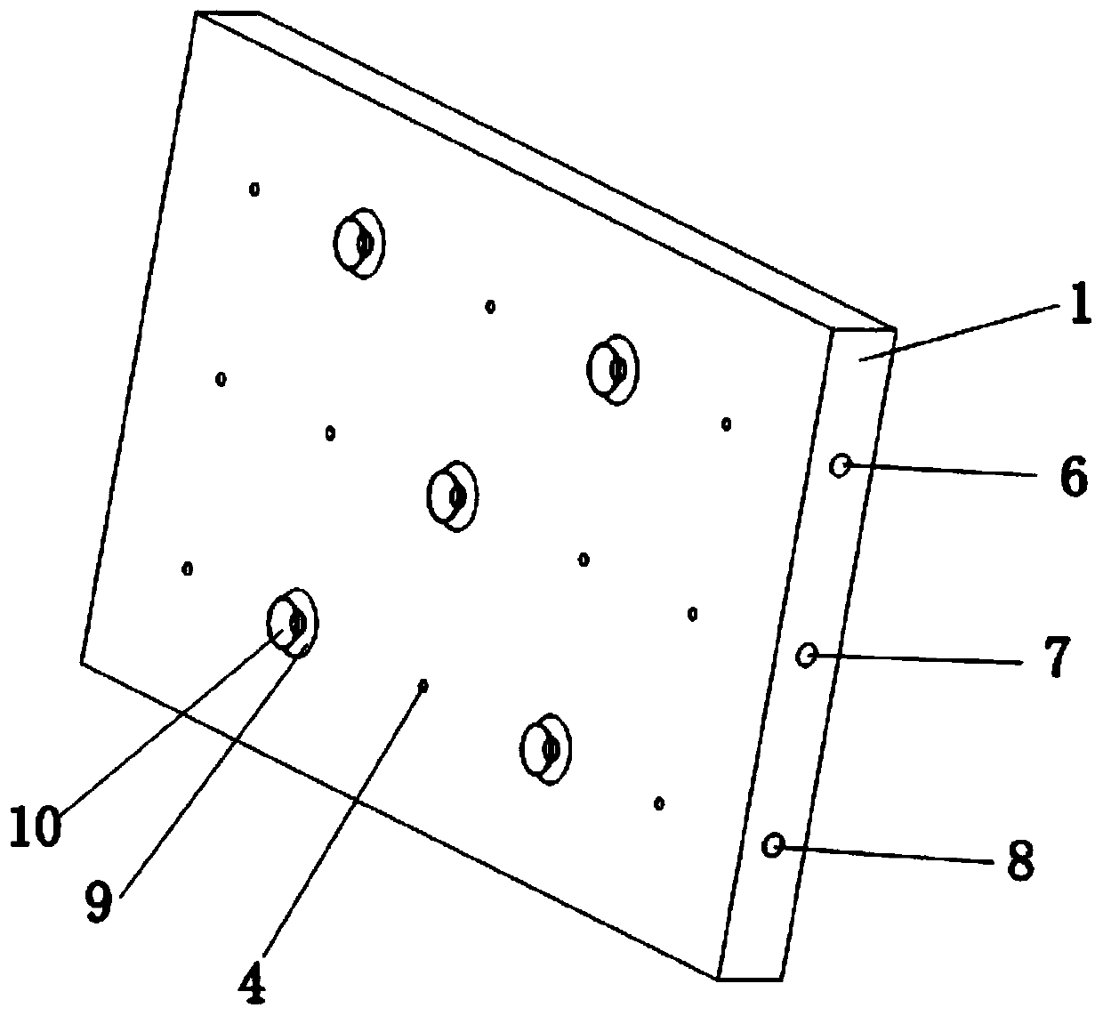
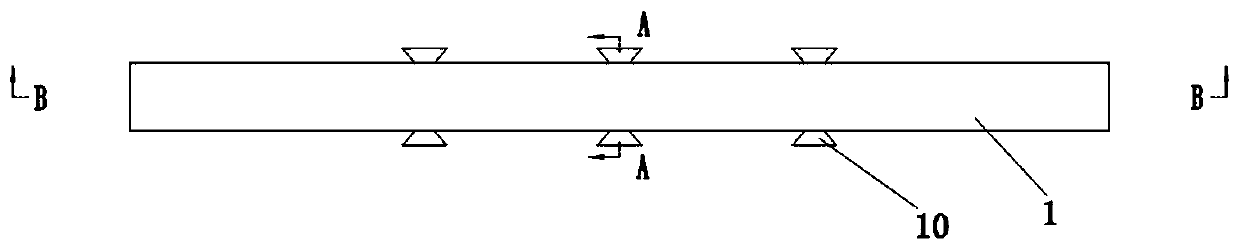
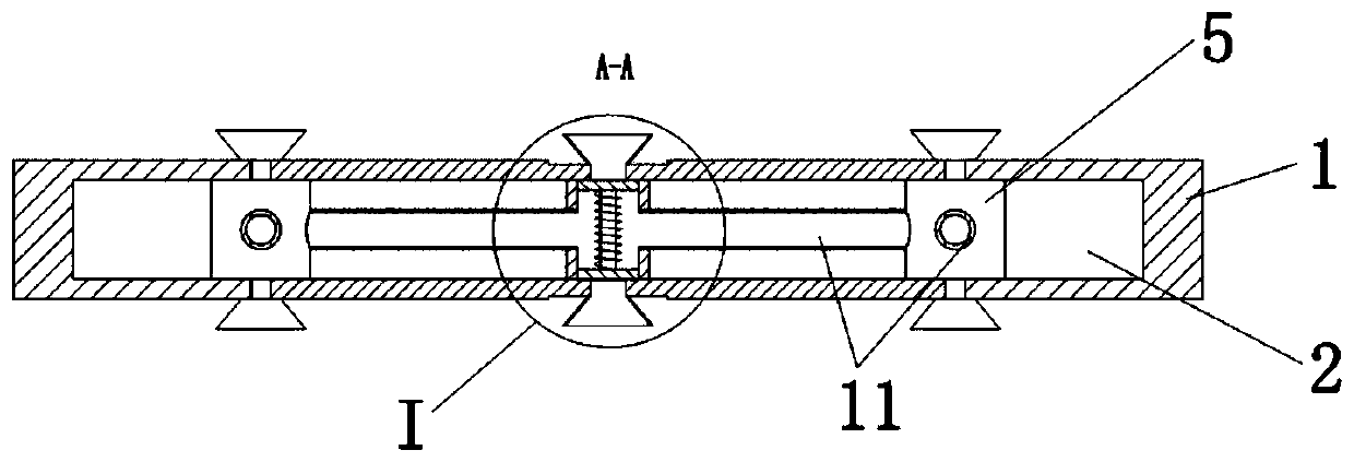
[0028] Such as Figure 1-5 A double-sided switching vacuum adsorption plate is shown, which includes a plate body 1 made of metal. The plate body 1 includes a first contact plate 101 and a second contact plate 102 opposite to each other. The plate body 1 is on the first contact plate 101. A chamber 2 is provided between the first contact plate 101 and the second contact plate 102. There are five groups of large adsorption holes 3 in the center of the plate body 1 and several evenly distributed small adsorption holes on the first contact plate 101 and the second contact plate 102. 4. An adsorption switching device 5 is fixed inside the chamber 2 , and a main suction port 6 , a secondary suction port 7 and an air intake port 8 are arranged on one side of the plate body 1 . Wherein, the auxiliary air inlet 7 communicates with the chamber 2, and the adsorption switching device 5 includes a sealing sleeve 501 and a telescopic rod 502 concentrically arranged with the large adsorptio...

Embodiment 2

[0030] When it is necessary to exchange and transfer workpieces on two opposite workbenches, for example, glass in a glass factory is placed vertically, and when glass of different quality needs to be replaced, the workpiece can be grasped by approaching one of the workbenches through the first contact plate 101 Picking, and then grabbing the workpiece close to another workbench through the second contact plate 102. At this time, it is not necessary to turn over the vacuum adsorption plate to realize double-sided switching vacuum adsorption grabbing, which greatly saves work efficiency.


PUM


Abstract

The invention provides a double-sided switching vacuum adsorption plate comprising a plate body. The plate body comprises a first contact plate and a second contact plate which are oppositely arrangedon the front face and the back face. The plate body is provided with a cavity between the first contact plate and the second contact plate. The first contact plate and the second contact plate are evenly provided with five groups of large adsorption holes at the center of the plate body and a plurality of evenly distributed small adsorption holes. An adsorption switching device is fixed into thecavity. The first contact plate and the second contact plate are provided with annular grooves at the positions corresponding to the large adsorption holes. Conical suction cups are fixed to the innerwalls of the large adsorption holes in a sealed manner. When the outer walls of the conical suction cups are completely attached to the inner walls of the grooves, the inner walls of the conical suction cups completely coincide with the outer surface of the first contact plate and the second contact plate. According to the double-sided switching vacuum adsorption plate, in the whole grabbing process of the workpiece, the manner of acting on the workpiece is to make soft contact with the workpiece first of fall and then increase adsorption force, so that the workpiece can be effectively protected and prevented from being damaged; and meanwhile, the adsorption effect is improved, production quality control is guaranteed, and the production efficiency is improved.

Description

technical field [0001] The invention relates to the field of grabbing devices, in particular to a double-sided switching vacuum adsorption plate. Background technique [0002] In the process of industrial grabbing, for some thinner flat structures, they cannot be handled normally, and a vacuum adsorption device is often required to use the principle of vacuum adsorption to grab the flat structure and then put it in a designated position. [0003] The existing vacuum adsorption plate needs to be in full contact with the workpiece before ensuring sufficient vacuum adsorption force to grab the plate structure. Not only must the flatness of the workpiece be good, but also the parallelism between the vacuum adsorption device and the surface of the workpiece must be ensured, which is also harmful to the operating environment. higher requirements. Otherwise, it will be considered that the contact is incomplete and the vacuum adsorption force is not uniform, which will cause the th...

Claims


Application Information

Patent Timeline
Patent Type & Authority Patents(China)
IPC IPC(8): B23Q1/66B23Q3/08
CPCB23Q1/66B23Q3/088
Inventor 杨海涛
Owner 深圳市粤海翔精密科技有限公司
Why Eureka
Try Eureka