AO total nitrogen removal device and total nitrogen removal process

A process, anoxic tank technology, applied in aerobic and anaerobic process treatment, chemical instruments and methods, water treatment parameter control, etc., can solve the problems of large volume of denitrification tank, large amount of carbon source added, and difficulty , to improve the denitrification efficiency, reduce the denitrification tank capacity, and maintain the stability.

Active Publication Date: 2020-01-17
苏州淡林环境科技有限公司
View PDF8 Cites 0 Cited by
  • Summary
  • Abstract
  • Description
  • Claims
  • Application Information

AI Technical Summary

Problems solved by technology

[0002] The N element contained in wastewater is an important factor for the eutrophication of water bodies, and it is also an important indicator for the control of sewage plants. Therefore, more and more attention has been paid to the improvement of total nitrogen. However, in the traditional denitrification process, there are often effluent The instability of total nitrogen, the large volume of denitrification tank required, the excessive addition of carbon sources, and the difficulty of further improving water quality for traditional denitrification processes, etc., all of these problems restrict the improvement of TN (total nitrogen) Important Factors for Retrofit
[0003] At present, the main processes for total nitrogen treatment are: AO denitrification process, oxidation ditch process, SBR process, MBR process, denitrification filter process, short-cut nitrification, anaerobic ammonium oxidation process, etc. These processes have their unique characteristics, but They also have their disadvantages, such as the low denitrification efficiency of the traditional AO process, the excessive tank capacity required by the oxidation ditch, the instability of the effluent treated by the SBR process, the high carbon source required by the denitrification filter, short-range nitrification and anammox The actual engineering application of process denitrification is immature, and these shortcomings are important factors restricting the upgrading and transformation of TN

Method used


Image

  • AO total nitrogen removal device and total nitrogen removal process
  • AO total nitrogen removal device and total nitrogen removal process
  • AO total nitrogen removal device and total nitrogen removal process

Examples


Embodiment Construction

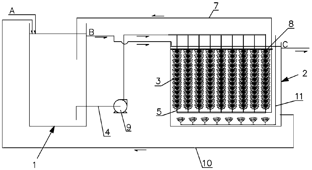
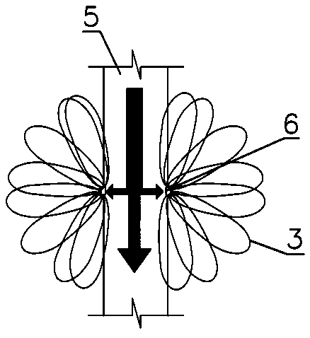
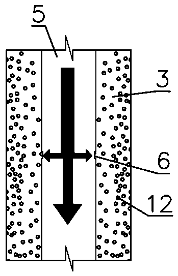
[0044] The technical solutions of the present invention will be clearly and completely described below in conjunction with the accompanying drawings. Apparently, the described embodiments are some of the embodiments of the present invention, but not all of them. Based on the embodiments of the present invention, all other embodiments obtained by persons of ordinary skill in the art without making creative efforts belong to the protection scope of the present invention.

[0045] In the description of the present invention, it should be noted that the terms "center", "upper", "lower", "left", "right", "vertical", "horizontal", "inner", "outer" etc. The indicated orientation or positional relationship is based on the orientation or positional relationship shown in the drawings, and is only for the convenience of describing the present invention and simplifying the description, rather than indicating or implying that the referred device or element must have a specific orientation, ...


PUM


Abstract

The invention relates to an AO total nitrogen removal device. The device comprises an anoxic tank and an aerobic tank; a filler is arranged in the aerobic tank; and a supply flow path is arranged between the anoxic tank and the interior of the filler. The invention also relates to an AO total nitrogen removal process. The process comprises the following steps: receiving sewage, and enabling the sewage to pass through an anoxic environment and an aerobic environment in sequence; setting the filler in the aerobic environment; and supplying a mixed VFA produced in the anoxic environment to the interior of the filler in the aerobic environment. The device and process can improve nitrogen removal efficiency.

Description

technical field [0001] The invention relates to a water treatment device, in particular to an AO total nitrogen removal device. The invention also relates to a total nitrogen removal process. Background technique [0002] The N element contained in wastewater is an important factor for the eutrophication of water bodies, and it is also an important indicator for the control of sewage plants. Therefore, more and more attention is paid to the improvement of total nitrogen. However, in the traditional denitrification process, there are often effluent The instability of total nitrogen, the large volume of denitrification tank required, the excessive addition of carbon sources, and the difficulty of further improving water quality for traditional denitrification processes, etc., all of these problems restrict the improvement of TN (total nitrogen) important factor in the transformation. [0003] At present, the main processes for total nitrogen treatment are: AO denitrification...

Claims


Application Information

Patent Timeline
Patent Type & Authority Applications(China)
IPC IPC(8): C02F3/30C02F3/10
CPCC02F3/101C02F3/30C02F3/305C02F2209/16Y02W10/10
Inventor 张勇范克高陈茂林冯晔丁本秀
Owner 苏州淡林环境科技有限公司
Why Eureka
Try Eureka