Integral synchronous jacking transformation method of overpass railway flyover

A technology of synchronous jacking and overpass, applied in the direction of bridges, bridge parts, bridge construction, etc., can solve the problems of long construction period, large safety risks and protection pressure of railway traffic, and minimum electrified catenary erection.

Inactive Publication Date: 2020-01-17
CHINA RAILWAY 14TH CONSTR BUREAU GRP 4TH ENG
View PDF6 Cites 14 Cited by
  • Summary
  • Abstract
  • Description
  • Claims
  • Application Information

AI Technical Summary

Problems solved by technology

[0002] With the development of the railway construction industry, many existing railways cannot meet the current operating requirements and need electrification transformation. During the electrification transformation process, the original clear height of the public-span railway overpass cannot meet the minimum clear height requirements for electrified catenary erection, etc. The problem, if according to the general traditional construction method is: protection of the overspan railway → demolition of the existing bridge → new construction in situ during the protection process
For the existing commercial line railways, due to the limited site conditions and the need to ensure the normal operation of the existing commercial line railways, the construction period in the process of demolition and new construction is longer, and the construction and construction costs are higher.
Due to the long construction period, it brings greater safety risks and protection pressure to railway traffic
Moreover, some construction processes are also restricted by the construction site, resulting in the inability to carry out construction on the existing business line railway line, which affects the development of the railway construction industry

Method used


Image

  • Integral synchronous jacking transformation method of overpass railway flyover
  • Integral synchronous jacking transformation method of overpass railway flyover
  • Integral synchronous jacking transformation method of overpass railway flyover

Examples


Embodiment Construction

[0127] In order to make the purpose, features, and advantages of the present invention more obvious and understandable, specific embodiments and drawings will be used to clearly and completely describe the technical solutions protected by the present invention. Obviously, the implementation described below The examples are only a part of the embodiments of the present invention, not all the embodiments. Based on the embodiments in this patent, all other embodiments obtained by those of ordinary skill in the art without creative work shall fall within the scope of protection of this patent.

[0128] The terminology used herein is only for describing specific embodiments, and is not intended to limit the expression in this document. As used herein, the singular forms "a", "an" and "the" are intended to include plural forms unless the context clearly dictates otherwise. It should also be understood that when used in this specification, the term "comprising" refers to the existence ...


PUM


Abstract

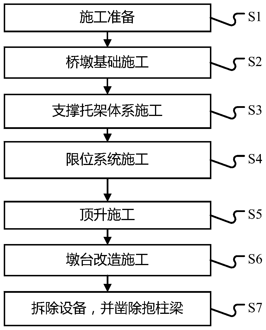
The invention provides an integral synchronous jacking transformation method of an overpass railway flyover. Jacks are jacked alternately, continuous operation can be achieved, and safety and controllability are achieved. Due to the fact that alternate jacking is adopted for jacking, in the jacking process of alternate jacking, the beam body is in the state that the two sets of jacks are alternately supported, when the two sets of jacks are alternately supported, the displacement of the beam body is in the controllable state, in each set of supporting state, the compression amount of the supporting system is hardly changed, and therefore the internal force of the beam body is hardly changed. In the operation mode, the displacement of the beam body is continuously in a controlled state fromthe beginning of jacking to the end of jacking. The pressure of each jack is continuously monitored, so that it can be ensured that the beam body can be prevented from being damaged in the jacking process, and the whole bridge jacking system is also in a safe and controllable state. The method is suitable for a series of projects which need to be integrally lifted for construction due to insufficient clearance under the existing flyover, navigation or other conditions.

Description

Technical field [0001] The invention relates to the technical field of bridge construction, in particular to an overall synchronous jacking transformation method for an upper-span railway overpass. Background technique [0002] With the development of the railway construction industry, many existing railways cannot meet the current operational requirements and require electrification. During the electrification process, the original clear height of the highway-span railway overpass will not meet the minimum clear height requirements of the electrified catenary. The question, if according to the general traditional construction method, it is: upper-span railway protection→existing bridge removal→in-situ construction during the protection process. For the existing business line railway, due to site conditions and the need to ensure the normal operation of the existing business line railway, the construction period during the demolition and new construction process is longer, and th...

Claims


Application Information

Patent Timeline
Patent Type & Authority Applications(China)
IPC IPC(8): E01D21/06E01D21/00E01D19/02
CPCE01D19/02E01D21/00E01D21/06
Inventor 李树敬
Owner CHINA RAILWAY 14TH CONSTR BUREAU GRP 4TH ENG
Why Eureka
Try Eureka