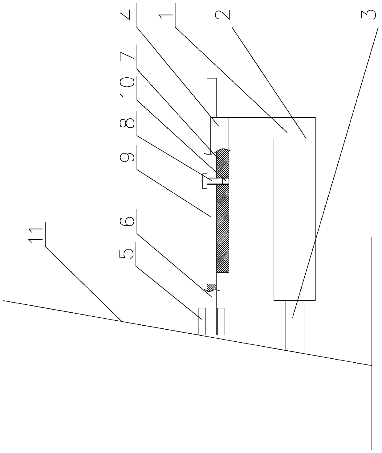
Process for breaking cast-in-place pile through ring cutting method

A cast-in-place pile and girth cutting technique, applied in sheet pile walls, infrastructure engineering, construction, etc., can solve the problems of low construction efficiency, affecting the overall durability of the structure, increasing noise and dust pollution, and avoiding structural strength. Effect

Inactive Publication Date: 2020-01-17
常州市市政建设工程集团有限公司
View PDF7 Cites 0 Cited by
  • Summary
  • Abstract
  • Description
  • Claims
  • Application Information

AI Technical Summary

Problems solved by technology

[0003] Nowadays, the rapid economic development has brought about the large-scale development of municipal projects, and the municipal construction in the city needs to consider the original roads or construction projects, so it is necessary to consider the safety, efficiency and cost of construction. Many traditional construction techniques have been Unable to meet existing construction status
[0004] There are two traditional techniques for removing cast-in-place piles. One is to use a gun head crusher to remove concrete from the top of the cast-in-place pile to the design elevation. This process removes the uneven height of the pile head, which cannot meet the design requirements and has low construction efficiency. , the construction period is long, and the long-term vibration operation will affect the overall durability of the structure, and will also increase noise and dust pollution; the second is to use an air compressor to peel off the concrete of the cast-in-situ pile protection layer to expose the steel bars, and then chisel it at the design elevation of the pile top. Concrete, separate the pile head from the pile body, and finally use a crane to lift the pile head out of the foundation pit. This method will have potential safety hazards when the pile head is separated from the pile body. At the same time, workers work in the foundation pit for a long time and have a high risk factor. The corners of the pile head plane are greatly damaged, and secondary construction must be carried out for modification, resulting in high cost and low construction efficiency

Method used


Image

  • Process for breaking cast-in-place pile through ring cutting method

Examples


Embodiment Construction

[0026] In order to understand the technical solutions provided by the present invention more clearly, the present invention will be further described below in conjunction with specific examples.

[0027] A kind of circumcision method provided by the present invention breaks cast-in-situ pile technology, its construction steps;

[0028] The first step is construction preparation, and the work preparation inside the foundation pit is carried out;

[0029] The second step is to prepare the equipment, adjust the construction equipment properly, and prepare for operation;

[0030] The third step is to measure the elevation and position, mark the design elevation of the pile head, and prepare for the construction work;

[0031] The fourth step is ring cutting construction. Ring cutting equipment is used to cut the pile head at the design elevation, and at the same time, the concrete is chiseled on the cutting seam to expose the steel bars;

[0032] The fifth step is to tilt the ma...


PUM


Abstract

The invention discloses a process for breaking a cast-in-place pile through a ring cutting method. The process comprises the construction steps that firstly, construction preparation is made; secondly, machines and tools are prepared; thirdly, the elevation is measured, and locating is conducted; fourthly, ring cutting construction is conducted; fifthly, a main reinforcement is inclined toward theouter side; sixthly, iron wedges are driven in around a pile head; seventhly, the pile head is lifted away from a foundation pit by a crane; eighthly, an inclined reinforcement is recovered; and ninthly, a site is cleaned. According to the provided process for breaking the cast-in-place pile through the ring cutting method, the ring cutting depth is located effectively through novel ring cuttingequipment, a blade can be prevented from cutting the main reinforcement in the pile head, and meanwhile, the conditions that in a traditional process, an air compressor is adopted, and structural strength of the pile head is influenced are avoided.

Description

technical field [0001] The invention relates to a technique for breaking cast-in-situ piles by ring cutting. [0002] technical background [0003] Nowadays, the rapid economic development has brought about the large-scale development of municipal projects, and the municipal construction in the city needs to consider the original roads or construction projects, so it is necessary to consider the safety, efficiency and cost of construction. Many traditional construction techniques have been Unable to meet the existing construction status. [0004] There are two traditional techniques for removing cast-in-place piles. One is to use a gun head crusher to remove concrete from the top of the cast-in-place pile to the design elevation. This process removes the uneven height of the pile head, which cannot meet the design requirements and has low construction efficiency. , the construction period is long, and the long-term vibration operation will affect the overall durability of th...

Claims


Application Information

Patent Timeline
IPC IPC(8): E02D9/00
CPCE02D9/005
Inventor 华文青王莹罗枭姜佳陈冬
Owner 常州市市政建设工程集团有限公司
Why Eureka
Try Eureka