
Deep foundation pit support construction process

A technology for deep foundation pit support and construction technology, which is applied in basic structure engineering, sheet pile walls, excavation, etc., can solve the difficult construction operation of construction personnel and excavation equipment, the occupation of deep foundation pit space, and the easy obstruction of construction by horizontal steel support. Personnel operation and other issues to achieve the effect of avoiding the reduction of support strength, reducing the deposition of rainwater, and avoiding soil erosion or collapse

Active Publication Date: 2020-01-17
SHENZHEN DONGSHEN ENG CO LTD
View PDF7 Cites 0 Cited by
  • Summary
  • Abstract
  • Description
  • Claims
  • Application Information

AI Technical Summary

Problems solved by technology

However, the horizontal steel support is horizontal in the middle of the deep foundation pit, so that the space in the deep foundation pit is occupied, so that the horizontal steel support easily hinders the construction personnel's operation, making it difficult for construction personnel and excavating equipment to carry out construction operations in the foundation pit.
[0005] The above existing technical solutions have the following defects: both the horizontal steel support method and the conventional double-row pile method are difficult to maintain the verticality of the side wall of the deep foundation pit while reducing the space occupied in the deep foundation pit

Method used


Image

  • Deep foundation pit support construction process
  • Deep foundation pit support construction process
  • Deep foundation pit support construction process

Examples


Embodiment Construction

[0035] The present invention will be described in further detail below in conjunction with the accompanying drawings.

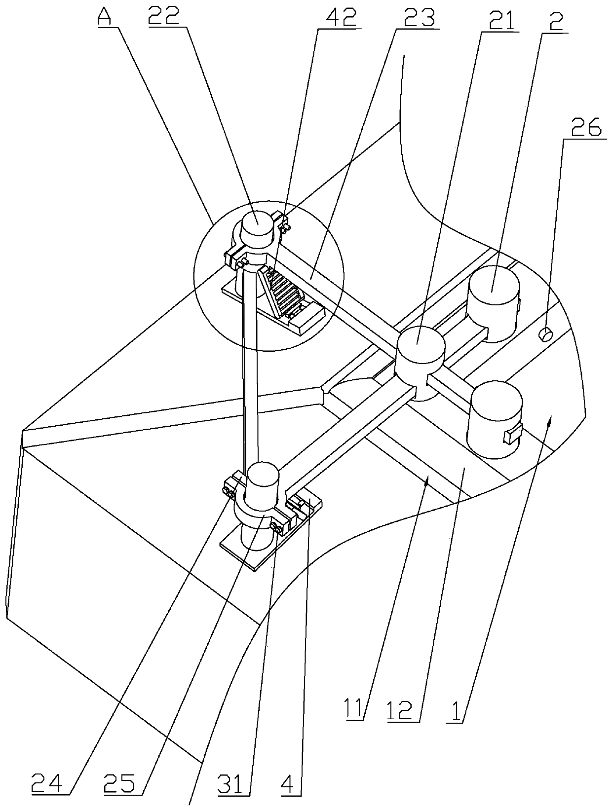
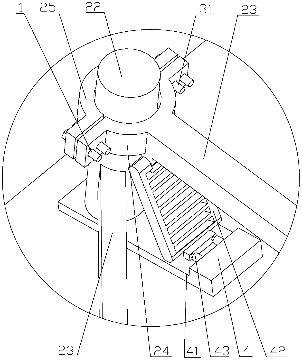
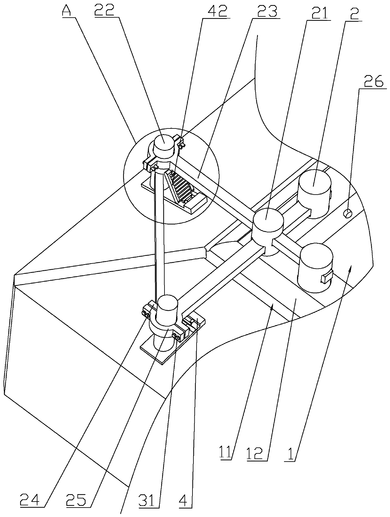
[0036] refer to figure 1 , is a deep foundation pit support construction process disclosed by the present invention, comprising the following steps: Step S100: firstly, at the construction site, a groove is pre-dug along the edge of the deep foundation pit 1, and concrete is poured in the groove to form an enclosure 12. The top surface of the enclosure 12 is arc-shaped, and its convex arc faces to the outside of the deep foundation pit 1, so that when the rainwater contacts the enclosure 12, it will flow to the outside of the deep foundation pit 1 under the guidance of the arc top surface. , so as to prevent rainwater from pouring back into the deep foundation pit 1 and affect the construction, and at the same time fix the edge of the deep foundation pit 1 to prevent objects such as stones from falling and causing casualties.

[0037] Afterwards, the enclosu...


PUM


Abstract

The invention relates to a deep foundation pit support construction process, and relates to the technical field of engineering facility construction. The deep foundation pit support construction process comprises the following steps that S100, a groove is pre-dug along the side line of a deep foundation pit on a construction site, an enclosure body is arranged, single-row piles are arranged on theinner side, close to the deep foundation pit, of the enclosure body, and the single-row piles are uniformly distributed in the extending direction of the side wall of the deep foundation pit; S200, fixing piles are arranged on the outer side, far away from the deep foundation pit, of the enclosure body, the fixing piles are arranged at the positions which are more than 5 meters away from the vertical distance of the enclosure body, and the bottom ends of the fixing piles are lower than the preset lowest position of the deep foundation pit; and S300, a horizontal steel frame is arranged between the fixing piles and the single-row piles, the two ends of the horizontal steel frame are connected with the fixing piles and the single-row piles respectively, and the length direction of the horizontal steel frame is perpendicular to the side wall of the deep foundation pit. The deep foundation pit support construction process has the effect that the perpendicularity of the side wall of the deep foundation pit can be improved under the condition that the space occupied in the deep foundation pit is reduced.

Description

technical field [0001] The invention relates to the technical field of engineering facility construction, in particular to a deep foundation pit support construction technology. Background technique [0002] Deep foundation pit refers to a project where the excavation depth exceeds 5 meters, or the depth does not exceed 5 meters, but the geological conditions, surrounding environment and underground pipelines are particularly complicated. In order to ensure the safety of the underground construction and the surrounding environment of the foundation pit, it is usually necessary to establish a supporting structure on the side wall of the deep foundation pit and the surrounding environment. [0003] At present, the deep foundation pit support structure usually adopts a double-row pile support structure. The double-row pile support structure is generally arranged along the side wall of the foundation pit, and is composed of two rows of support piles and beams connected by the fr...

Claims


Application Information

Patent Timeline
Patent Type & Authority Applications(China)
IPC IPC(8): E02D17/04E02D5/22
CPCE02D5/22E02D17/04
Inventor 覃辉煌吴翠萍文建生傅朝成
Owner SHENZHEN DONGSHEN ENG CO LTD
Learn More