
Open pile control device

A technology of pile clamping and clamping piles, which is applied in the direction of sheet pile walls, buildings, foundation structures, etc., can solve the problems that cannot meet the requirements of the verticality of pile formation and the control of prefabricated pipe piles at the speed of pile unloading, etc., and achieve the solution of clamping load Evenly distributed loading and the effect of improving pile quality

Inactive Publication Date: 2012-04-25
SUNWARD INTELLIGENT EQUIP CO LTD +2
View PDF8 Cites 6 Cited by
  • Summary
  • Abstract
  • Description
  • Claims
  • Application Information

AI Technical Summary

Problems solved by technology

[0004] However, the adjustment of the existing pile-holding and clamping technology in terms of verticality of pile entry, clamping force, and pile entry speed cannot meet the requirements of the large-diameter drilling-while-drilling and tubular pile construction method on the verticality of pile formation, pile unloading speed, and during construction. Requirements for the control of prefabricated pipe piles

Method used


Image

  • Open pile control device
  • Open pile control device
  • Open pile control device

Examples


Embodiment 1

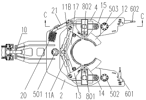
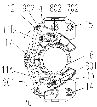
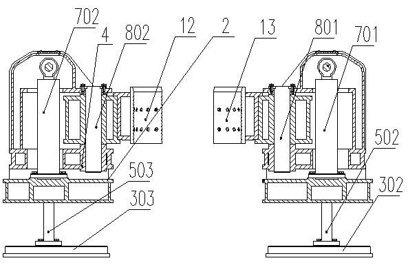
[0029] Such as Figure 1 to Figure 6 In the pile controller shown in Embodiment 1, one end of the connecting plate 1 is connected to the pile controller through a sliding sleeve 19, and the other end is hinged to the waist-shaped hole of the lug of the main machine for pile foundation construction through a pin 18. The connecting plate 1 can slide in the sliding sleeve 19; the pile controller can rotate up and down around the pin shaft 18, and can slide along the waist hole, so as to adapt to the posture change when the pile controller is vertically adjusted , to ensure the accuracy of the pile hole position. The first platform 2 is the supporting part of the pile control device. One end of the oil cylinder seat of the two pressure-drawing cylinders 701, 702 is fixed on the first platform 2. The pile clamping platform 4 above the platform 2 is hinged, and the expansion and contraction of the pressing and pulling oil cylinders 701 and 702 can drive the lifting of the pile clam...

Embodiment 2

[0032] Such as Figure 7 to Figure 11In the pile controller shown in Embodiment 2, one end of the sliding rod 10 is connected to the pile controller and can slide axially on the first platform 2; The pile control device can rotate around the spherical hinge point and slide along the waist-shaped hole. This connection method has more degrees of freedom, and can completely compensate for the composite angle and position changes caused by the vertical adjustment of the pile control device, which is convenient for pile control. The device is aligned with the pile position. The first platform 2 is the supporting part of the pile control device. One end of the oil cylinder seat of the two pressure-drawing cylinders 701, 702 is fixed on the first platform 2. The pile clamping platform 4 above the platform 2 is hinged, and the expansion and contraction of the pressing and pulling oil cylinders 701 and 702 can drive the lifting of the pile clamping platform 4 and the pile clamping mec...


PUM


Abstract

The invention relates to an open pile control device, which comprises a first platform, a pile clamp platform positioned above the first platform, pressing and pulling oil cylinders, a first pile clamp, a second pile clamp, a third pile clamp, pile clamping oil cylinders, pull rods, at least three leveling oil cylinders, leveling bottom plates, and a connecting mechanism, wherein the first pile clamp and the second pile clamp are hinged with the pile clamp platform and are respectively hinged with the third pile clamp through the pull rods, and the pile clamping oil cylinders are hinged with the first pile clamp and the second pile clamp; the first pile clamp and the second pile clamp are pushed by the oil cylinders to rotate around pin shafts of the first pile clamp and the second pile clamp, and drive the third pile clamp to move so as to clamp or loosen a pipe pile, and the leveling bottom plates with the same number of the leveling oil cylinders are positioned below the first platform; piston rods of the leveling oil cylinders are hinged with the leveling bottom plates, and the attitude of the first platform is controlled by adjusting the extension of the leveling oil cylinders; and the connecting mechanism is used for connecting the pile control device with a pile foundation construction host.

Description

technical field [0001] The invention relates to a device for placing and removing piles in pile foundation construction, in particular to a pile guiding pile controller. Background technique [0002] At present, a new type of construction method for large-diameter pipe piles while drilling has emerged: the reaming drill bit is connected to the drill pipe and then penetrates into the inner hole of the prefabricated pipe pile. At the bottom of the pile, the diameter is enlarged and the soil is excavated to form a hole. The diameter of the hole drilled by the reaming drill bit is slightly larger than the outer diameter of the prefabricated pipe pile. After reaching the set depth, the drilling tool is pulled out from the prefabricated pipe pile hole, and the concrete is poured. This kind of construction method has high pile forming efficiency, large bearing capacity, environmental protection, and has great development prospects. [0003] In the existing pile foundation constru...

Claims


Application Information

Patent Timeline
Patent Type & Authority Applications(China)
IPC IPC(8): E02D11/00
Inventor 朱建新唐孟雄吴新荣单葆岩
Owner SUNWARD INTELLIGENT EQUIP CO LTD
Learn More