Diagonal reinforcement structure of reinforced concrete beam-column joint

A technology of reinforced concrete and beam-column joints, which is applied to building structures, structural elements, building components, etc., can solve problems such as damage to concrete, increased shear force, and small degree of external convex expansion, and achieves enhanced seismic performance and enhanced resistance to Clipping performance, reducing the effect of input

Active Publication Date: 2020-01-17
NINGBO NOTTINGHAM NEW MATERIALS INST CO LTD +1
View PDF5 Cites 2 Cited by
  • Summary
  • Abstract
  • Description
  • Claims
  • Application Information

AI Technical Summary

Problems solved by technology

The above-mentioned common form of reinforcement has defects: in order to enhance the shear strength of the joint area and realize the design idea of ​​"strong joint, weak member", the number of transverse stirrups is bound to increase, which will cause congestion in the core area of ​​the joint , the construction is inconvenient, and in extreme cases, even compact concrete cannot be vibrated, which affects the seismic performance of beam-column joints
[0006] In this way, since the inclined section of the additional reinforcement is anchored and bonded in the concrete in the core area of ​​the joint, the additional reinforcement on both sides will inevitably transmit the tensile force received by the horizontal section on both sides into the concrete in the joint area through the inclined section, thereby affecting The concrete in the node area is damaged; moreover, the concrete on both sides of the other diagonal direction is compressed and the pressure is transmitted to the concrete in the core area, so that the diagonal direction forms a concrete oblique compression bar, that is, the concrete in the diagonal direction will be compressed due to Expand radially outward along the diagonal, and the middle of the diagonal expands more outwardly while the two ends of the diagonal expand outwardly less, thus forming a spindle-shaped oblique bar, which will naturally further damage the nodes The concrete in the area reduces the joint strength and seismic performance; moreover, the horizontal and vertical shear resistance of the two inclined sections of the two diagonal additional reinforcements anchored in the joint concrete is still insufficient, and there is still a probability of shear failure; secondly, The length of the horizontal section where the additional reinforcement is anchored in the beam concrete on both sides of the node is also debatable. If the length is too short, the anchorage length of the additional reinforcement will be insufficient, resulting in the force transmitted through the additional reinforcement not meeting the structural requirements. However, if the length of the horizontal section is large , the gradient and fall of reinforcement in the beam are not obvious, so that the plastic hinge of the beam is too close to the node area to move outward, or even simply located on the interface between the node area and the beam, which will cause the stress of the beam rotation to penetrate into the node area , and the input shear force will also increase, further increasing the damage risk of the node area

Method used


Image

  • Diagonal reinforcement structure of reinforced concrete beam-column joint
  • Diagonal reinforcement structure of reinforced concrete beam-column joint
  • Diagonal reinforcement structure of reinforced concrete beam-column joint

Examples


Embodiment Construction

[0020] The present invention will be further described below in conjunction with the accompanying drawings and specific embodiments.

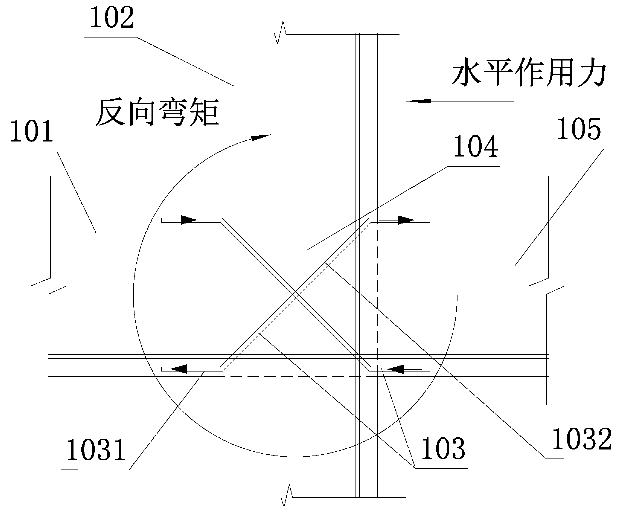
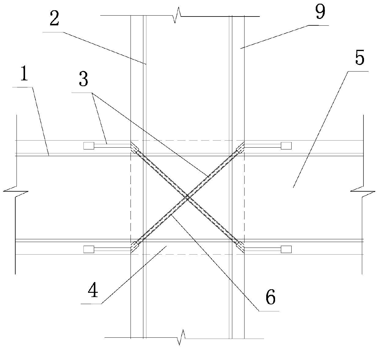
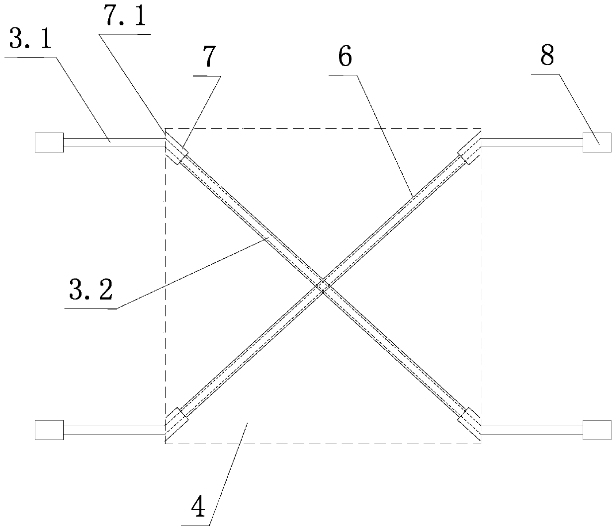
[0021] Such as figure 2 , image 3 As shown, the diagonal reinforcement structure of the reinforced concrete beam-column joint of the present invention includes the transverse main reinforcement 1 of the beam 5 passing through the node area 4 and the vertical main reinforcement 2 of the column 9 . The diagonal reinforcement structure also includes two additional reinforcements 3, and each additional reinforcement 3 is composed of horizontal sections 3.1 on both sides and an inclined section 3.2 in the middle. The inclined section 3.2 in the middle of each additional rib 3 is located in the concrete of the node area 4, and the two inclined sections 3.2 of the two additional ribs 3 intersect to form a diagonal arrangement.

[0022] The outer gap of the inclined section 3.2 of each additional rib 3 is fitted with a steel casing 6, and a hollow ...


PUM


Abstract

The invention discloses a diagonal reinforcement structure of a reinforced concrete beam-column joint. The diagonal reinforcement structure comprises a transverse main rib and a vertical main rib which penetrate through a joint region, and further comprises two additional ribs. Each additional rib is composed of horizontal sections on the two sides and an inclined section in the middle, wherein the horizontal sections on the two sides are anchored in beam concrete on the two sides of the joint region correspondingly, and the inclined section in the middle is located in the concrete of the joint region. The two inclined sections of the two additional ribs are arranged in a crossed and diagonal mode. The inclined section of each additional rib is sleeved with a steel sleeve in a clearance mode. The two ends of each steel sleeve are each provided with a hollow anchor head. The outer diameter of each anchor head is larger than the outer diameter of the corresponding steel sleeve. The steelsleeves and the anchor heads are all anchored in the concrete in the joint region. By means of the structure, the permeation of the stress of the stressed area of a beam into the joint region by thestressed additional ribs can be reduced, meanwhile inclined pressed rods formed through pressing in the other diagonal direction in the joint region are effectively constrained, and the anti-shearingperformance in longitudinal and transverse directions of the joint can be enhanced.

Description

technical field [0001] The invention relates to the technical field of reinforced concrete frame structure construction, in particular to a diagonal reinforcement structure of reinforced concrete beam-column joints. Background technique [0002] In the reinforced concrete beam-column frame structure, the part where the columns and beams intersect vertically and horizontally is the node area, which is also called the node core area in the industry. The joint area is internally reinforced and covered with a concrete protective layer. The reinforcement of the joint area usually includes the transverse main reinforcement of the beam passing through the joint area, the vertical main reinforcement of the column and several transverse stirrups hooping the vertical main reinforcement. The above-mentioned common form of reinforcement has defects: in order to enhance the shear strength of the joint area and realize the design idea of ​​"strong joint, weak member", the number of trans...

Claims


Application Information

Patent Timeline
Patent Type & Authority Applications(China)
IPC IPC(8): E04C5/06E04B1/20E04B1/21
CPCE04B1/20E04B1/21E04C5/0604
Inventor 李波沈新宇陈永苍
Owner NINGBO NOTTINGHAM NEW MATERIALS INST CO LTD
Why Eureka
Try Eureka