Compressor and air conditioner

A compressor and shaft technology, applied in the field of air conditioning, can solve the problems of increased wear of parts, poor stability of rotor compressors, and noise, and achieve the effects of reducing friction, reducing movement, and reducing noise

Pending Publication Date: 2020-01-17
ZHUHAI GREE REFRIGERATION TECH CENT OF ENERGY SAVING & ENVIRONMENTAL PROTECTION
View PDF0 Cites 4 Cited by
  • Summary
  • Abstract
  • Description
  • Claims
  • Application Information

AI Technical Summary

Problems solved by technology

In the prior art, no reliable fixing measures are taken in the axial direction of the crankshaft, so that the movement of the crankshaft in the axial direction cannot be well suppressed, resulting in poor stability of the rotor compressor during operation, and exacerbating zero Wear between parts, while creating noise problems

Method used


Image

  • Compressor and air conditioner
  • Compressor and air conditioner
  • Compressor and air conditioner

Examples


Embodiment Construction

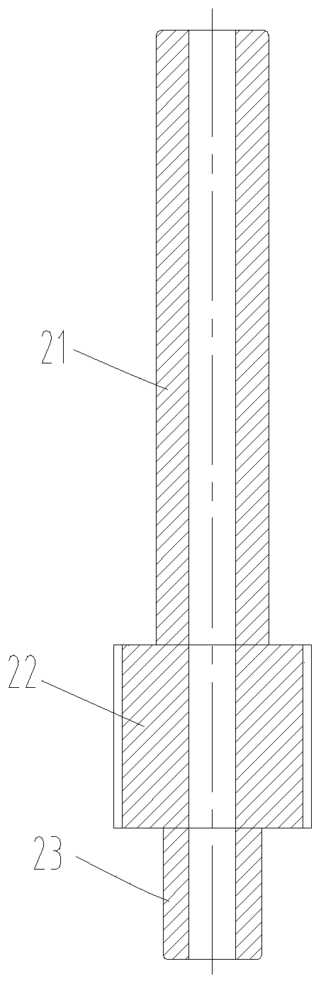
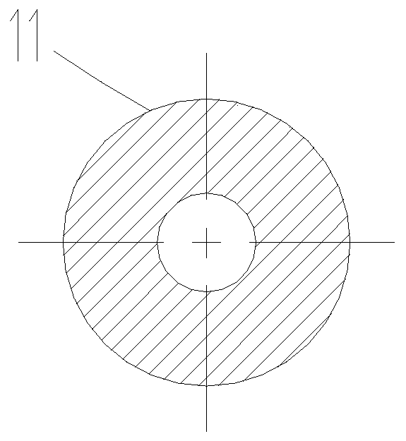
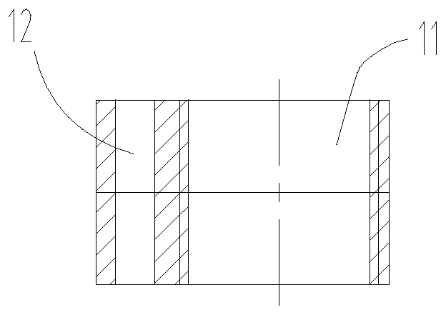
[0024] see in conjunction Figure 1 to Figure 5 As shown, according to the embodiment of the present application, a compressor includes a rotating shaft 2 and a cylinder 6, the rotating shaft 2 passes through the cylinder 6, and the first flange 4, the second flange 5 and the roller 1 are sleeved on the rotating shaft 2 , the roller 1 is located in the cylinder 6, the first flange 4 is set on the first end of the cylinder 6, the second flange 5 is set on the second end of the cylinder 6, the cylinder 6, the first flange 4 and the second The flange 5 limits the position of the roller 1, the roller 1 is provided with a first limiter, and the crankshaft is provided with a second limiter, and the first limiter cooperates with the second limiter to be able to The axis direction of the rotating shaft 2 fixes the rotating shaft 2 and the roller 1 . By setting the cylinder 6, the first flange 4 and the second flange 5 are arranged at both ends of the cylinder 6, and the roller 1 is a...


PUM


Abstract

The invention provides a compressor and an air conditioner. The compressor comprises a rotating shaft and an air cylinder. The rotating shaft penetrates through the air cylinder, the rotating shaft issleeved with a first flange, a second flange and a roller, the roller is located in the air cylinder, the first flange is arranged at the first end of the air cylinder in a covering manner, the second flange is arranged on the second end of the air cylinder in a covering manner, the roller is limited inside through the air cylinder, the first flange and the second flange, the roller is provided with a first limiting part, a crankshaft is provided with a second limiting part, the first limiting part and the second limiting part are matched, and a rotating shaft and the roller are fixed in theaxis direction of the rotating shaft. According to the compressor, moving of the crankshaft during work in the axial direction can be reduced, the compressor can more stably work, friction between parts can be reduced, and meanwhile, noise generated during work of the compressor can be reduced.

Description

technical field [0001] The application belongs to the technical field of air conditioning, and in particular relates to a compressor and an air conditioner. Background technique [0002] Existing rotary compressors include a driving power device and a compression device that lifts the refrigerant into high-pressure gas. The power device and the compression device are connected through the interference fit between the crankshaft and the motor rotor. The motor rotor drives the crankshaft to rotate, and then drives the roller to rotate in the cylinder to realize the work of the rotor compressor. [0003] When the compressor runs at high speed, the rotor of the motor is affected by the pressure pulsation, and it is easy to move in the axial direction, which in turn drives the crankshaft to move in the axial direction. In the prior art, no reliable fixing measures are taken in the axial direction of the crankshaft, so that the movement of the crankshaft in the axial direction ca...

Claims


Application Information

Patent Timeline
Patent Type & Authority Applications(China)
IPC IPC(8): F04C18/00F04C29/00
CPCF04C18/00F04C29/00F04C29/0035F04C2240/20F04C2240/80
Inventor 孙晓梅赵庆富杨欧翔徐嘉
Owner ZHUHAI GREE REFRIGERATION TECH CENT OF ENERGY SAVING & ENVIRONMENTAL PROTECTION
Why Eureka
Try Eureka